
Optical fiber continuation loss and solutions
The transmission loss characteristics of optical fibers are the first of the most critical factors in determining the optical data transmission distance, transmission reliability and reliability. There are various reasons for the loss of optical fiber transmission of laser cutting machine. In the basic construction and maintenance of optical fiber communication Internet, the most important concern is the reason of transmission loss caused by optical fiber application and how to reduce this loss.
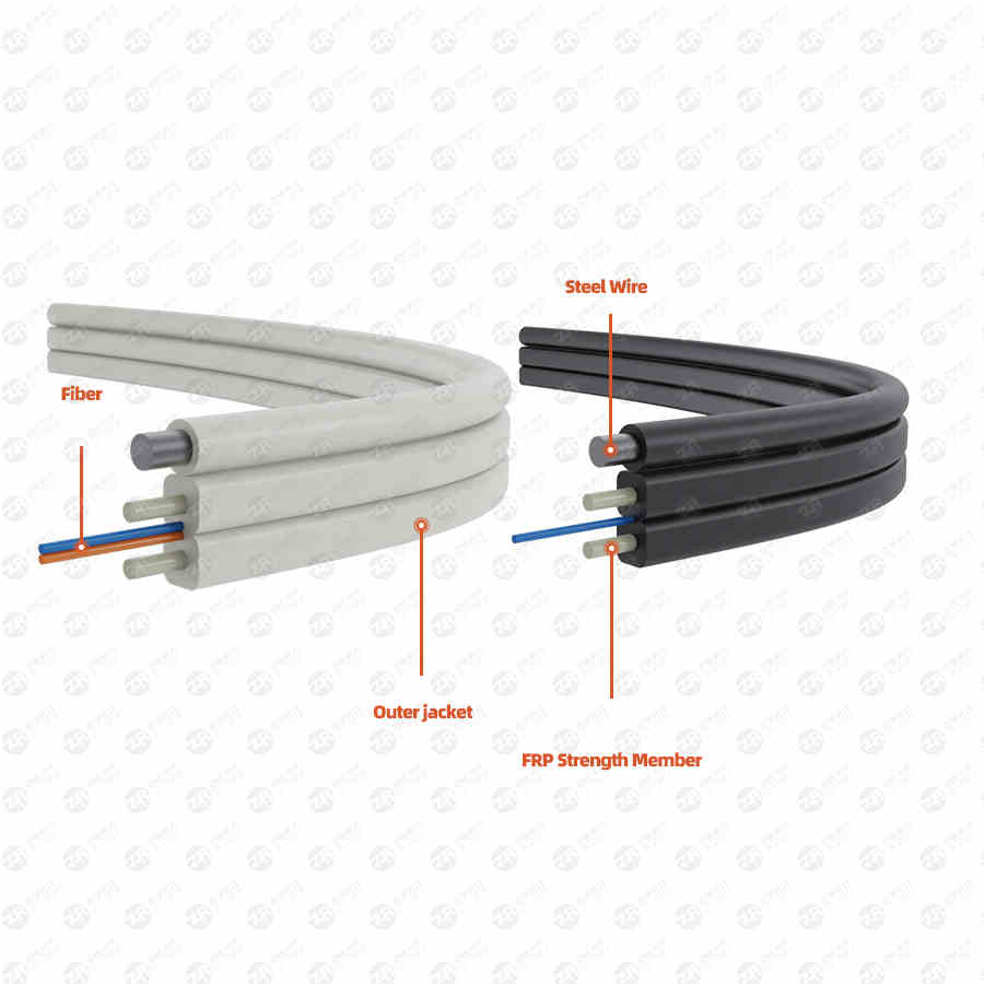
The transmission loss caused in the application of optical fiber mainly includes continuous loss (the loss of optical fiber, fusion loss and thematic activity connector loss) and discontinuous loss (bending loss and loss caused by other engineering construction elements and application scenarios). .
Optical fiber continuation loss and solutions
1.1 Continued wear and tear
The continuous loss of the optical fiber includes: the loss caused by the intrinsic factor of the optical fiber, the fusion loss caused by the extrinsic factor, and the loss of the theme active connector.
(1) The main reason for the loss of optical fiber is that the diameter of the optical fiber mode field is different; the core diameter of the optical fiber is mismatched; the cross section of the fiber core is not round; The field diameters are not the same.
(2) The fusion loss of non-intrinsic elements of fusion loss is mainly caused by radial displacement; pivot (folding angle) skew; inner hole is separated (void); fiber inner hole is not detailed; refractive index difference; fiber inner hole is not cleaned and It is caused by other factors such as the continuation of the actual operation level of the staff, the operation process, the welding machine-level cleaning level, the basic parameters of welding, and the cleaning level of the office environment.
(3) The main components of the active connector wear and tear of the non-intrinsic elements are mainly caused by the poor quality, looseness, and non-cleaning of the active RF connector and some of the same elements as the welding loss (such as radial displacement, internal Pore voids, chamfers, refractive index differences, etc.).
1.2 Plans for dealing with continual wear and tear
(1) High-quality optical fibers with the same characteristics should be used in architectural engineering design, engineering construction and maintenance work. On this route, high-quality and well-known brand bare fibers with the same batch number should be used as much as possible, and the characteristics of optical fibers should be matched as much as possible, so that The effect of mode field diameter on fiber splice loss is minimized.
(2) The construction of optical cable projects should be carried out in strict accordance with technical specifications and regulations
When arranging disks, ensure that the entire disk is equipped as much as possible (single disk ≥ 500 meters), so as to avoid the total number of connectors as much as possible. When laying, it is strictly issued according to the serial number and terminal order of the cable reel, so that the loss value exceeds the minimum.
(3) Select extension staff who have rich experience and are not chaotic in the face of danger to carry out extension and testing
The level of extension workers immediately affects the size of the extension loss. Extension workers should strictly implement the fiber splicing production process to carry out extension, strictly control the loss of the connector, and use the Optical Domain Reflectometer (OTDR) to carry out detection (continuation loss) during the whole process of fusion. ≤0.08dB/piece), those that do not meet the requirements should be welded again. When applying optical time domain reflectometry (OTDR), it is necessary to accurately measure the loss of the connector from two directions, and calculate the average value of the two results to eliminate the human error bias of the accurate measurement of unilateral OTDR.
(4) Ensure that the continuation of the natural environment meets the regulations
It is forbidden to actually operate outdoors in a dusty and wet and cold natural environment. The connection position of the optical cable, small tools and raw materials should be clean, and the optical fiber connector should not be allowed to return to moisture. The optical fiber prepared for laser cutting in advance must be cleaned, and there should be no waste. After laser cutting, the optical fiber should not be exposed to the gas for too long, especially in the dusty, humid and cold natural environment. When the continuous working temperature is too low, the necessary temperature raising countermeasures should be adopted.
(5) Preparation of a sound optical fiber inner hole
The production of the inner hole of the optical fiber is a more important technological process for the continuation of the optical fiber. Whether the soundness of the inner hole of the optical fiber is the first key reason for determining the continuous loss of the optical fiber. The high-quality inner hole should be leveled, free of burrs, no damage, and vertical to the centerline. The inclination angle of the centerline of the fiber inner hole should be less than 0.3 degrees, showing a mirror glass that is smooth and level, and clean to prevent Dust environment pollution. A high-quality cleaver should be obtained and properly used to laser cut fibers. The cleaning, laser cutting and melting strategy of bare fibers should be inseparably connected, and the spacing should not be too long. When moving the fiber, handle it with care to avoid damage to the inner hole of the fiber due to rubbing with other objects.
(6) Proper application of fusion splicer
Proper application of the fusion splicer is a key guarantee and an important link to reduce the continuous loss of optical fibers.
①The operation guide and operation steps of the fusion splicer should be strictly implemented, and the fusion splicer should be properly operated.
②Effectively place the optical fiber. When placing the optical fiber in the V-groove of the fusion splicer, the posture should be light. This is because for a single-mode fiber with a core diameter of 10 nm, if the fusion splicing loss is to be lower than 0.1 dB, the axial deviation of the fiber centerline must be lower than 0.8 nm. ③According to the type of optical fiber, the main parameters of welding (pre-charge and discharge current, time, main charge and discharge current, main charge and discharge time, etc.) should be properly and effectively set.
④ Dust in the fusion splicer should be removed immediately after use (especially the soot and fiber debris from the fixture, mirror glass and v-shaped groove body).
⑤ The service life of the welding electromechanical stage is usually about 2000 times. After a long application time, the electric stage will be oxidized by the air, resulting in a slightly larger charge and discharge current and an increase in the welding loss value. At this time, you can remove the electric stage, gently scrub with ethanol-dipped medical equipment absorbent cotton, and then put it on the fusion splicer, and charge and discharge it for many times. If the charge and discharge current is still slightly larger after several cleanings, the battery must be replaced again.
(7) Use high-quality and qualified flexible RF connectors as much as possible to ensure that the performance parameters of the RF connectors meet the relevant requirements. The insertion loss of the flexible connector should be controlled below 0.3dB/piece (or even lower), and the additional loss should not exceed 0.2dB/pc
(8) The theme activity connector should be connected to the light wire with good quality, and the coupling should be inseparable to avoid light transmission.
(9) Make sure that the RF connector of the theme activity is cleaned up
During construction and maintenance, attention should be paid to cleaning up the power plug and power adapter (flange) and ensure the cleaning of the main engine room and the natural environment of machinery and equipment. Resolutely prevent the power plug and power adapter (flange) from having waste and dust. Avoid optical scattering losses.
