
Summary of fiber splicing knowledge
The preparation of the fiber end face includes the steps of stripping, cleaning and cutting. A qualified fiber end face is a necessary condition for fusion splicing, and the quality of the end face affects the quality of fusion splicing.
2. Stripping of the optical fiber coating
Master the three-character stripping method of smooth, steady and fast. "Flat" means to keep the fiber flat. The thumb and index finger of the left hand pinch the optical fiber to make it horizontal, and the exposed length should be 5cm. The remaining fiber is naturally bent between the ring finger and the little finger to increase the strength and prevent slipping. "Stable" means that the fiber stripper should be held firmly. "Fast", that is, the fiber should be stripped quickly. The fiber stripper should be perpendicular to the fiber, tilted upward at a certain angle inward, and then lightly clamp the fiber with the jaws. The right hand will follow with force and push it out along the axis of the fiber. The whole process To be natural and smooth, in one go.
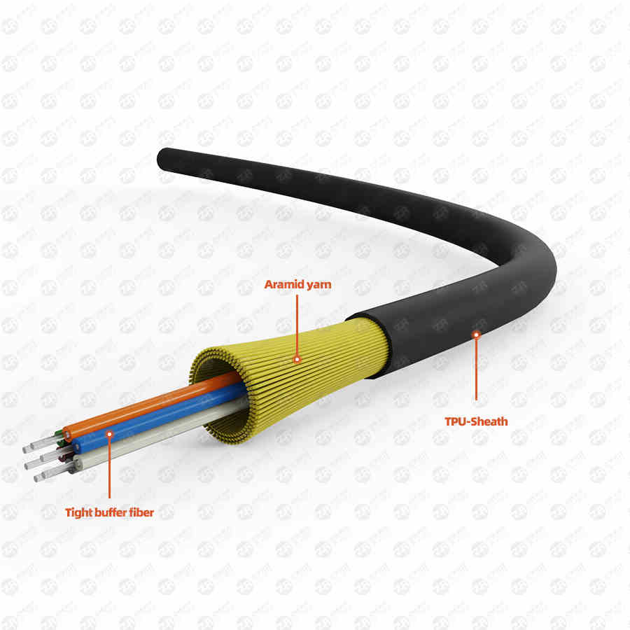
Fiber splicing
3. Bare fiber cleaning
The cleaning of bare fibers should follow the steps below.
1) Observe whether the coating layer of the stripped part of the fiber is completely stripped, if there is any residue, it should be stripped again. If there is a very small amount of coating that is not easy to peel off, you can use a cotton ball to dip an appropriate amount of alcohol, dipping it, and gradually wipe it off.
2) Tear the cotton into a flat fan-shaped piece, dip it in a little alcohol (it is advisable to pinch two fingers together without overflowing), fold it into a V" shape, clamp the stripped fiber, wipe it along the axis of the fiber, and try to do it once. If it is successful, a piece of cotton should be replaced in time after 2 to 3 times of use, and different parts and layers of cotton should be used each time, which can not only improve the utilization rate of cotton, but also prevent the two pollution of fiber detection.
3) Cutting of bare fibers
Cutting is the most critical part in the preparation of optical fiber endfaces. Precise and excellent cutters are the foundation, and strict and scientific operating specifications are the guarantee. for effective cutting.
4. Knife selection
There are two types of cutting knives, manual and electric. The former is simple to operate and has reliable performance. With the improvement of the operator's level, the cutting efficiency and quality can be greatly improved, and the bare fiber is required to be shorter, but the environmental temperature difference is higher. The latter has higher cutting quality and is suitable for operation in cold conditions in the field, but the operation is more complicated, the working speed is constant, and the bare fiber is required to be longer.
Skilled operators should use manual cutters for fast optical cable connection or emergency rescue at room temperature; on the contrary, for beginners or when working in colder conditions in the wild, electric cutters are suitable.
5. Operation Specifications
Operators should be specially trained to master the essentials of action and operating specifications. First of all, clean the cutter and adjust the position of the cutter. The placement of the cutter should be stable. When cutting, the action should be natural and stable, not heavy or urgent, to avoid the occurrence of bad end faces such as broken fibers, bevels, burrs, and cracks. In addition, learn to "play the piano", reasonably distribute and use your right fingers, make them correspond and coordinate with the specific parts of the cutter, and improve the cutting speed and quality.
6. Beware of end-face pollution
The heat shrinkable sleeve should be penetrated before peeling, and it is strictly forbidden to penetrate after the end face is prepared. The cleaning, cutting and splicing time of bare fiber should be closely connected, and the interval should not be too long, especially the prepared end face should not be placed in the air. When moving, handle it with care to prevent it from rubbing against other objects. During the connection, according to the environment, the "V"-shaped groove, pressure plate and blade edge of the cutter should be cleaned to prevent end face pollution.
7. Welding procedure
Before splicing, according to the material and type of the optical fiber, set key parameters such as the optimal pre-melting main fusing current and time and the amount of fiber feeding. During the welding process, the "V" groove, electrodes, objective lens, welding chamber, etc. of the welding machine should also be cleaned in time. Observe whether there are air bubbles, too thin, too thick, virtual melting, separation and other undesirable phenomena in the welding at any time. Pay attention to the tracking and monitoring results of the OTDR. Timely analyze the causes of the above-mentioned undesirable phenomena and take corresponding improvement measures. If the phenomenon of virtual fusion occurs many times, check whether the materials and models of the two optical fibers to be spliced match, whether the cutter and the fusion splicer are polluted by dust, and check the oxidation status of the electrodes. If there is no problem, the fusion current should be appropriately increased.
Eight, coil fiber
Coiling fiber is a technology and an art. The scientific method of coiling fiber can make the fiber layout reasonable, the additional loss is small, can withstand the test of time and harsh environment, and can avoid fiber breakage caused by extrusion.
fiber coil rule
1) The fiber is coiled along the loose tube or the branching direction of the optical cable. The former is suitable for all splicing projects; the latter is only suitable for the end of the main optical cable, and it is one in and multiple out. The branches are mostly small logarithmic cables. The rule is to reel the fiber once every time after splicing and heat shrinking one or several optical fibers in loose tubes, or optical fibers in a sub-technical direction optical cable. Advantages: It avoids the confusion of optical fibers between loose optical fiber tubes or between different branched optical cables, so that the layout is reasonable, easy to install, easy to disassemble, and more convenient for future maintenance.
2) Take the heat-shrinkable tube placement unit in the reserved tray as the unit to coil the fiber. This rule is to coil the fiber according to the number of heat-shrinkable tubes that can be placed in a small placement area in the reserved tray in the splice box. For example, the GLE type barrel splice box, in actual operation, every 6 cores is a plate, which is extremely convenient. Advantages: It avoids the unevenness of the same bundle of optical fibers caused by different placement positions, difficulty in coiling and fixing, and even sharp bends and small circles.
3) In special cases, such as optical splitters, add/drop pigtails, pigtails and other special devices in the connection, it is necessary to first splicing, heat shrinking, and coiling ordinary optical fibers, and then deal with the above situations in turn. disc operation to prevent an increase in additional losses caused by squeezing.
fiber optic method
1) First the middle and then the two sides, that is, place the heat-shrinked sleeves in the fixing grooves one by one, and then deal with the remaining fibers on both sides. Advantages: It is beneficial to protect the optical fiber contacts and avoid possible damage caused by the coiled fiber. This method is often used when the optical fiber reserved disk space is small and the optical fiber is not easy to coil and fix.
2) Start the fiber coil from one end, that is, start from the fiber coil on one side, fix the heat shrinkable tube, and then process the remaining fiber on the other side. Advantages: The placement position of the effective copper pipe can be flexibly selected according to the length of the residual fiber on one side, which is convenient and fast, and can avoid the phenomenon of sharp bends and small circles.
3) Handling of special cases, such as individual fibers are too long or too short, they can be coiled separately at the end; when there are special optical devices, they can be treated separately. If they are co-coiled with ordinary fibers, they should be coiled It is placed lightly on the ordinary optical fiber, and a buffer pad is added between the two to prevent the fiber from being broken due to extrusion, and the pigtail of the special optical device should not be too long.
4) According to the actual situation, a variety of graphic fiber coils are used. According to the length of the residual fiber and the size of the reserved disk space, coil it naturally according to the trend, do not pull it hard, and flexibly use circle, ellipse, "CC", "~" various shapes of coil fiber (note that R≥4cm), as large as possible Make maximum use of the reserved disk space and effectively reduce the additional loss caused by the disk fiber.
Nine, the quality assurance of optical cable connection
Strengthening the monitoring of OTDR is of great significance to ensure the splicing quality of optical fibers and reduce the additional loss caused by the coiled fibers and the damage that may be caused to the optical fibers by the sealing box. In the whole continuous work, the four monitoring procedures of OTDR must be strictly implemented:
1) Real-time tracking and monitoring of each core fiber during the fusion process to check the quality of each fusion point;
2) After each coiled fiber, conduct an example inspection on the coiled fiber to determine the additional loss caused by the coiled fiber;
3) Before sealing the splicing box, conduct a unified test on all optical fibers to find out whether there is any leakage and whether the optical fibers and connectors are squeezed between the optical fiber reserved disks;
4) After sealing the box, perform a final inspection on all optical fibers to check whether the sealing box has any damage to the optical fibers.
10. Technical Issues
main factors. There are many factors that affect the loss of optical fiber fusion, which can be roughly divided into two categories: intrinsic factors and extrinsic factors of optical fibers.
1. The intrinsic factor of the fiber refers to the factor of the fiber itself, and there are four main points.
(1) The fiber mode field diameter is inconsistent;
(2) The core diameters of the two optical fibers are mismatched;
(3) The core section is not round;
(4) The concentricity between the core and the cladding is not good.
Among them, the inconsistency of fiber mode field diameter has the greatest impact. According to the recommendation of CCITT (Consultation Committee for International Telegraph and Telephone), the tolerance standard of single-mode fiber is as follows:
Mode field diameter: (9~10μm)±10%, that is, the tolerance is about ±1μm;
Cladding diameter: 125±3μm;
Mode field concentricity error ≤6%, cladding out-of-roundness ≤2%.
2. The extrinsic factor that affects the optical fiber splice loss is the splice technology.
(1) Axial misalignment: The single-mode fiber core is very thin, and the axial misalignment of two butt-jointed fibers will affect the splice loss. When the misalignment is 1.2μm, the splicing loss reaches 0.5dB.
(2) Inclination of the axis: When the optical fiber section is inclined by 1°, a splice loss of about 0.6dB will be generated. If the splice loss is required to be ≤0.1dB, the inclination angle of the single-mode fiber should be ≤0.3°.
(3) End face separation: The connection of the movable connector is not good, and it is easy to cause end face separation, resulting in large connection loss. When the discharge voltage of the fusion splicer is low, end face separation is also likely to occur, which can generally be found in fusion splicers with a tensile test function.
(4) End face quality: When the flatness of the fiber end face is poor, loss and even air bubbles will occur.
(5) Physical deformation of the optical fiber near the splice point: the tensile deformation of the optical cable during the erection process, and the pressure of clamping the optical cable in the splice box is too high, which will affect the splice loss, and even several times of fusion can not be improved.
3. The influence of other factors.
The operation level of the splicer, the operation steps, the fiber coil process level, the cleanliness of the electrodes in the fusion splicer, the splicing parameter settings, and the cleanliness of the working environment will all affect the value of the splicing loss.
measures to reduce losses
1. Try to use the same batch of high-quality brand-name bare fibers on a line
For the same batch of fibers, the mode field diameters are basically the same. After the fiber is disconnected at a certain point, the mode field diameters between the two ends can be regarded as the same. impact is minimized. Therefore, fiber optic cable manufacturers are required to use the same batch of bare fibers, continuously produce them according to the required length of the fiber optic cable, and sequentially number and distinguish the A and B ends on each reel, without skipping numbers. When laying the optical cable, it must be laid out according to the number along the determined routing sequence, and ensure that the B end of the optical cable in the front coil is connected to the A end of the optical cable in the next coil, so as to ensure that the connection can be spliced at the disconnection point, and the splice loss value reaches minimum.
2. Optical cable erection shall be carried out as required
In the construction of optical cable installation, it is strictly forbidden to make small circles, fold and twist the optical cable. More than 80 people must construct the 3km optical cable, and more than 100 people must construct the 4km construction, and be equipped with 6 to 8 walkie-talkies; The new cable laying method can effectively prevent the occurrence of back buckle. The traction force shall not exceed 80% of the allowable optical cable, and the maximum instantaneous traction force shall not exceed 100%. The traction force should be added to the strength member of the optical cable. The optical cable should be laid in strict accordance with the construction requirements of the optical cable, so as to minimize the probability of the optical fiber being damaged during the construction of the optical cable, and avoid the increase of the fusion loss caused by the damage of the optical fiber core.
3. Select experienced and well-trained optical fiber connection personnel for connection
Most of the welding is automatically welded by the welding machine, but the level of the connecting personnel directly affects the size of the connecting loss. The splicing personnel should strictly follow the optical fiber splicing process flow chart, and during the splicing process, they should use the OTDR to test the splice loss of the splicing point while splicing. Those that do not meet the requirements should be spliced again. For the point with a larger splicing loss value, the number of repeated splicing should be 3 to 4 times.
4. The connection of the optical cable should be carried out in a clean environment
It is strictly forbidden to operate in the open air in a dusty and humid environment. The connecting parts of the optical cable, tools and materials should be kept clean, and the optical fiber connector should not be damp. The optical fiber to be cut must be clean and free of dirt. After cutting, the fiber must not be exposed to air for too long, especially in dusty and humid environments.
5. Use a high-precision fiber end face cutter to prepare the fiber end face
The quality of the fiber end face directly affects the size of the splice loss. The cut fiber should be a flat mirror surface without burrs and defects. The inclination angle of the fiber end face should be less than 1 degree. A high-precision fiber end face cutter not only improves the success rate of fiber cutting, but also improves the quality of the fiber end face. This is especially important for fusion splices that cannot be tested by the OTDR (ie, blind spots in the OTDR test) and fiber maintenance and repair.
6. Correct use of fusion splicer
The function of the fusion splicer is to splicing two optical fibers together, so the correct use of the fusion splicer is also an important measure to reduce the optical fiber splice loss. Correctly and reasonably set the splicing parameters, pre-discharge current, time, main discharge current, main discharge time, etc. according to the fiber type, and remove the dust in the fusion splicer in time during and after use, especially the fixture, mirrors and v-groove Removal of dust and fiber debris inside. Before each use, the welding machine should be placed in the welding environment for at least fifteen minutes, especially in places where the placement and use environment are quite different (such as indoor and outdoor in winter). , reset the discharge voltage and discharge position of the fusion splicer, and reset the v-slot driver.
11. Conclusion
The continuous operation of optical cables is a meticulous work, especially in the aspects of end face preparation, welding, fiber coiling, etc., which requires the operator to observe carefully, consider carefully, and operate in a standardized way. In short, in the work, it is necessary to cultivate a rigorous and meticulous work style, diligently summarize and think, in order to improve practical operation skills, reduce connection loss, and comprehensively improve the quality of optical cable connection.
