
Submarine optical fiber performance requirements
Submarine optical cables require long-distance, low-attenuation transmission, and they must adapt to the environment of the seabed. The requirements for resistance to water pressure, air loss, stretch resistance, and impact resistance are particularly strict. Therefore, the optical fibers used for submarine optical cables are higher than those used for terrestrial optical cables. Optical fibers have higher requirements; they require low loss, high strength, long manufacturing lengths, and are required to withstand strong pressure and tension.
The structure of the deep-sea optical cable is relatively complex: the optical fiber is set in the plastic skeleton of the U-shaped groove, and the groove is filled with grease or elastic plastic body to form the fiber core. The core is wrapped with high-strength steel wire. During the wrapping process, all the gaps should be filled with waterproof material, and then a layer of copper tape is wrapped around the steel wire and welded lap seams, so that the steel wire and the copper tube form an anti-resistant material. A combination of compression and tension.
A polyethylene jacket is also added to the outside of the steel wire and copper pipe. Such a dense multi-layer structure is to protect the optical fiber, prevent breakage and prevent the intrusion of seawater. In shark-infested areas, a polyethylene jacket is added to the outside of the cable.
submarine cable
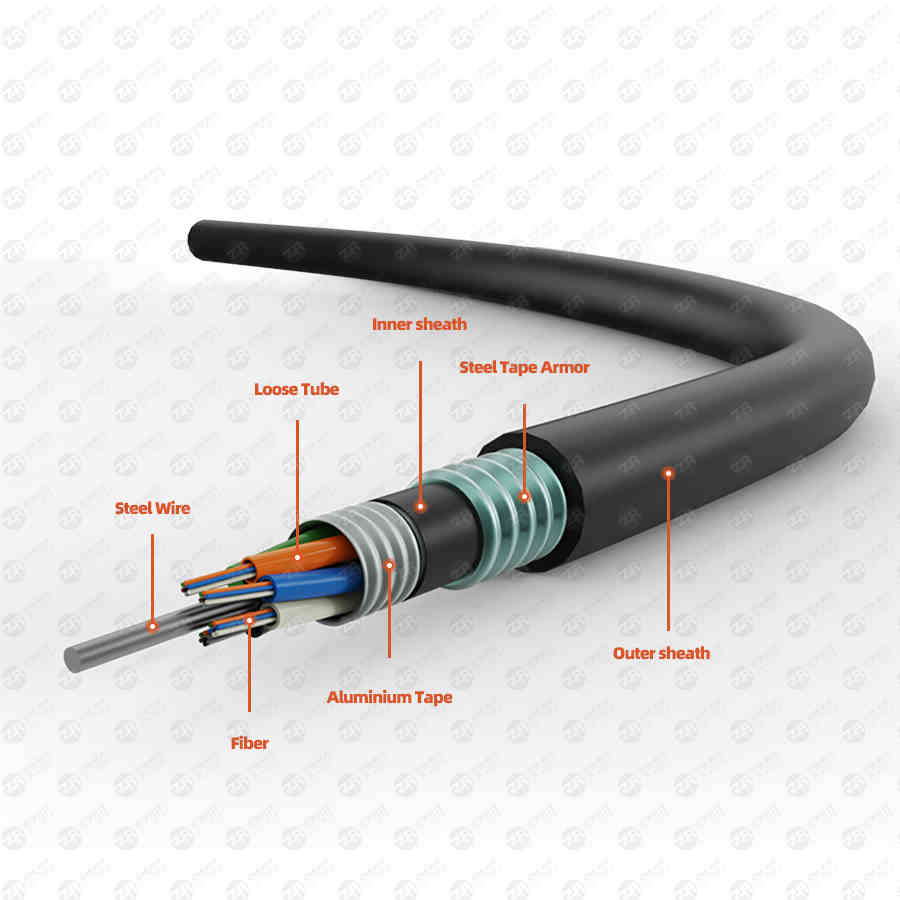
Structural Analysis of Typical Submarine Optical Cables
1. Polyethylene layer
Special requirements for submarine cables
Whether it is the design of the terrestrial optical cable or the design of the submarine optical cable, it is to ensure that the optical fiber works in a relatively stable and safe environment, and can achieve long-term and stable transmission of optical signals without external interference. Different environments have different requirements for the production of optical cables. The submarine optical cable design must ensure that the optical fiber is not affected by external forces and the environment. The basic requirements are: it can adapt to the environment such as submarine pressure, wear, corrosion, and biology;
There is a suitable armor layer to prevent the damage of fishing trawls, anchors and sharks; when the optical cable is broken, the length of the seawater infiltrating into the optical cable is minimized; it can prevent the hydrogen from penetrating into the optical cable from the outside and the hydrogen generated inside; it has a Low-resistance remote power supply circuit; can withstand the tension during laying and recycling; the service life is generally required to be more than 25 years.
Performance requirements and production process optimization of optical fibers in submarine optical cables
Submarine optical cables require long-distance and low-attenuation transmission, and they must adapt to the environment of the seabed. The requirements for resistance to water pressure, gas loss, stretch resistance, and impact resistance are particularly strict. The transmission capacity of optical fiber is large, and the distance between relay stations is long, which is suitable for long-distance communication on the seabed. In order to meet these specific requirements, the basic structure of the submarine optical cable is to wrap the optical fiber after one or two coating treatments in the center, around the reinforcement member (made of steel wire), and put it in a special stainless steel tube. In the middle, the high-strength arched steel wire is wrapped around the tube, and the steel wire layer is covered with copper tube, so that no micro/macro bending occurs when the optical cable is laid.
Finally the outer sheath is extruded. Although the manufacturing process of the submarine cable avoids the micro/macrobending loss of the optical fiber during the laying process of the submarine cable, the unevenness in the production process of the submarine cable makes the longitudinal extrusion of the metal or grease uneven on the optical fiber, resulting in The external stress on the optical fiber is uneven, so as to minimize the attenuation of the optical fiber and achieve longer-distance transmission. Optical fibers used in submarine optical cables have higher requirements than those used in terrestrial optical cables; they require low loss, high strength, long manufacturing lengths, and are required to withstand strong pressure and tension.
The nominal working wavelength of the submarine cable system should be C-band (1530-1560nm) or C+L (1530-1625nm) band. At present, the attenuation of conventional single-mode fibers produced by many manufacturers can reach 0.19dB/km at 1550nm. Even below, it is very close to the theoretical limit value of silica fiber. Therefore, for the optical fiber for submarine cable, in addition to the optical transmission performance, it is mainly necessary to consider reducing the microbending loss of the fiber, high strength, and large coil length. Improve the screening strength and screen out optical fibers with better performance.
1. Optimize the microbending performance of the fiber
With the increasing application of the 1625nm wavelength, it is more and more important to increase the macrobend and microbend performance of the optical fiber in the L-band (1560-1625nm). The macrobending loss of the fiber unit during use is negligible, and the microbending loss of the fiber needs to be paid close attention.
The contact surface of the optical fiber is unevenly squeezed, resulting in micro-bending of the order of μm or less than mm, which leads to an increase in the micro-bending loss of the optical fiber. The transmission loss of micro-bending is mainly caused by mode coupling.
Fibers with microbending loss have significantly higher attenuation values at 1625nm or even 1550nm than those without bending. It can be seen that microbend loss has a great impact on long wavelength attenuation, especially in submarine cables that require long distances and low In the attenuation communication system, how to control the microbend loss is particularly important.
The refractive index of the inner coating of the optical fiber is larger than that of the quartz glass and the elastic modulus is lower (several hundred MPa), which can buffer the external stress well. The ideal value of the coating diameter is about 190 μm; the curing degree of the coating also affects the microbending resistance of the optical fiber. If the curing of the coating is too low, it will affect the attenuation, appearance and subsequent processes of the optical fiber. It will cause the degradation of the optical fiber coating, so the curing degree must be controlled within an appropriate range, which varies with the coatings used;
In addition, the concentricity of the coating will also affect the microbending performance of the optical fiber, which requires the coating of the optical fiber to be uniform. It is recommended to use the wet-on-wet coating method. Save space and increase the natural cooling space of bare optical fibers. On the other hand, the concentricity of the optical fibers produced by wet coating is also very good. This depends on the adjustment of the mold before use. The concentricity online monitoring device can be installed to fine-tune the mold online. In order to achieve a better coating effect, the inner coating with better concentricity can evenly buffer the external pressure and reduce the microbending loss of the optical fiber.
In addition to the influence of the above factors on the microbending loss of the optical fiber, the performance of the coating itself also has a great influence on the microbending performance of the optical fiber. Figure 4 shows the high and low temperature cycle of the optical fiber produced by different coating systems. At -60 ℃, the low temperature performance of different fibers is very different, and the performance of the coating itself is very important to the fiber. Microbending performance has a large impact, so choosing a coating with good performance is critical to producing high-quality optical fibers.
2. High strength, large disc length
Compared with ordinary optical cables, the optical fiber unit of submarine cable has the main performance improvement of high strength and large coil length in addition to optical transmission performance. In the process of laying, using, salvaging and being subjected to unexpected external forces, the optical fiber is protected by the external structure of the optical cable, but it still has to bear certain strain and residual stress. Therefore, in order to prevent the destructive effect of laying, maintenance and accidental tension on the optical fiber unit, the optical fiber for submarine optical cable must have higher strength than the optical fiber for ordinary optical cable; and the large coil length is to reduce the number of connectors within the relay distance, try to Make the length of the cable reel consistent with the relay distance of the system.
Commonly used single-mode fibers are made of silica glass, which has a theoretical breaking stress of 20 GPa. However, due to the influence of various factors, there will be a certain number of microcracks on the surface of the optical fiber, and the stress concentrated on the crack tip will cause the optical fiber to break at a lower stress level. The optical fibers are subjected to various stresses when they are manufactured into optical cables, as well as in the laying, use, and maintenance of optical cables.
In order not to break the optical fiber under these stresses, a certain stress must be applied to the optical fiber produced after drawing, so as to screen out the weak points on these optical fibers in advance. The strength of the fiber is related to the number of these weak points. The length of the optical fiber is not only affected by the above reasons, but also affected by the uniformity of optical fiber geometry and optical parameters. In view of these influencing factors, and taking into account the special requirements of optical fibers used in submarine optical cables, the corresponding optimization of raw materials and drawing processes is mainly carried out.
(1) Optimization of raw materials
As the most important raw material in optical fiber production, preform is an extremely important factor affecting the quality of optical fiber. The uniformity of the optical parameters and geometric parameters of the preform directly affects the uniformity of the optical and geometric parameters of the optical fiber, and also affects the maximum coil length that the optical fiber can produce. It ensures the relative uniformity of the geometric and optical parameters of the preform in a long distance, and also ensures the uniformity of the optical and geometric parameters of the optical fiber in a long distance, that is to say, the optical fiber with a large coil length can be produced.
In addition, no matter whether you buy the preform wire drawing or make your own wire drawing, in the process of transportation and storage of the preform, the surface of the preform will be more or less contaminated and cause defects. These contaminations and defects will have a greater impact on the quality of the drawn optical fiber. Some of these pollutants are organic components (such as grease and sweat secreted on hands, mold release agent on packaging bags, etc.) that cannot be completely removed by ordinary wiping and cleaning.
It will decompose at high temperature in the drawing furnace and react with silicon dioxide to form components such as silicon carbide with a higher melting point than silicon dioxide, or produce crystallization components at lower temperatures, so that the surface of the optical fiber is directly generated. a huge defect, which affects the strength of the fiber.
As for those inorganic contaminants, there is a similar effect on fiber strength. Similarly, in the process of transportation and storage of the preform, there will also be small defects caused by collision and scratches on the surface of the preform. It is relatively short and cannot be fully healed in the molten state in the drawing furnace, so that undue defects are formed on the surface of the drawn optical fiber, which in turn affects the strength of the optical fiber.
In view of this situation, for the preform to be drawn, oxyhydrogen flame polishing can be adopted to greatly reduce the occurrence of such defects. At high temperature, the rich hydrogen in the oxyhydrogen flame reacts with silicon dioxide to produce easily evaporated silicon monoxide and water, which are then taken away by the high-speed oxyhydrogen flame airflow, and at the same time, the pollutants on the surface of the preform are taken away. Because in the polishing process, the oxyhydrogen flame is actually used to throw away dozens of microns of silicon dioxide from the surface of the preform, so the microcracks on the surface of the preform are also healed. As for larger defects, due to the high temperature The cause has been fixed to the greatest extent possible. Therefore, the surface condition of the preform is greatly improved, and the strength problems caused by surface defects and contamination of the preform are reduced.
(2) Optimization of wire drawing process
Optical fibers produced by the same raw material under different drawing processes have obvious differences. Therefore, for optical fiber products that require high strength and large coil length, there are also special requirements for the drawing process.
As the place where the preform is smelted into optical fiber, the drawing furnace needs to be protected by a large amount of inert gas. The flow distribution of the gas and the amount of gas have a great impact on the strength of the optical fiber. In the high temperature environment in the drawing furnace, the graphite parts will produce some tiny solid particles (usually their own volatiles and graphite particles generated after long-term airflow scouring), and the inert protective gas used in the furnace will also carry some solid impurities. (usually solid particles in gas pipelines or gas storage containers).
If these solid particles collide with the fragile bare fiber under the action of the airflow, some microcracks, that is, weak points, will be generated on the surface of the fiber, which will have a great impact on the strength of the fiber. Therefore, in addition to strict requirements on the number of volatiles, density and surface roughness of graphite parts, we also filter the inert protective gas before entering the drawing furnace to ensure the cleanliness of the gas.
At the same time, we have carried out a series of optimizations on the air flow in the drawing furnace, so that the gas moves strictly in a laminar flow mode, so that the particles generated by the graphite parts are swept by the air flow to avoid contact with the molten glass and optical fibers. The track is taken out of the furnace or attached to the inner wall of the lower part of the drawing furnace; at the same time, the airflow is prevented from blowing directly to the melting area of the glass and the optical fiber forming area, so as to prevent the solid particles in the gas from adhering to the surface of the molten glass or colliding with the formed optical fiber, reducing the The generation of surface microcracks increases the strength of the fiber.
After the optical fiber comes out of the high temperature area of the drawing furnace, we optimize the cooling method of the optical fiber to reduce the residual stress in the optical fiber and reduce the expansion of micro-cracks due to residual stress, resulting in more weak points. At the same time, the reduction of residual stress also has a positive impact on the optical parameters of the optical fiber and reduces the photoelastic effect, which is also of positive significance for the improvement of the PMD value.
For the coating of UV coatings for optical fibers, we have carried out corresponding optimizations. According to the properties of different coatings, the coating temperature and coating pressure are optimized to improve the uniformity of the coating and the bonding performance between the coating and the bare fiber; at the same time, we have improved the UV curing system and optimized the curing oven. The gas and the irradiation direction of the ultraviolet light ensure the uniformity of the curing performance and the appropriateness of the curing degree of the optical fiber coating in all directions.
These improvements improve the bonding ability of the coating and the bare fiber, strengthen the coating's ability to compensate for micro-cracks on the surface of the fiber, and also improve the strength of the fiber to a certain extent, and also reduce the residual stress in the coating. It reduces the microbending effect caused by the local unevenness of the coating stress, reduces the local optical fiber optical parameter unevenness caused by the microbending effect, and increases the length of the optical fiber coil.
By optimizing the raw materials and the drawing process, we have reduced the screening breakpoint rate of the optical fiber to about 2‰.
(3) Optimization of the screening process
Considering the particularity of the operating environment of the submarine optical cable, there are special requirements for the strength of the optical fiber. Therefore, in the screening process, we have implemented strict requirements for optical fibers used in submarine optical cables. The general optical fiber adopts a screening tension of 100 kilo-pound per square inch (Kpsi), and the screening strain is 1%, while for optical fiber used in submarine cables, we increase the screening tension to 200 kilo-pound per square inch (Kilo-pound per square inch, Kpsi). poundpersquareinch, Kpsi), the screening strain is greater than 2%, which is twice that of ordinary optical fibers, avoiding the existence of low-strength points. After adopting such screening process requirements, we can still provide large coil length fibers with screening lengths up to 100 kilometers, which is four times that of ordinary fibers.
