
Basic knowledge of optical fibers and cables
1. Briefly describe the composition of optical fibers.
A: An optical fiber consists of two basic parts: the core and cladding made of transparent optical material, and the coating.
2. What are the basic parameters that describe the transmission characteristics of optical fiber lines?
A: Including loss, dispersion, bandwidth, cutoff wavelength, mode field diameter, etc.
3. What is the cause of fiber attenuation?
Answer: The attenuation of a fiber refers to the reduction in optical power between two cross-sections of a fiber, which is related to the wavelength. The main causes of attenuation are scattering, absorption, and optical losses due to connectors and splices.
4. How is the fiber attenuation coefficient defined?
Answer: Defined by the attenuation (dB/km) per unit length of a uniform fiber in steady state.
5. What is insertion loss?
Answer: It refers to the attenuation caused by inserting optical components (such as inserting connectors or couplers) in the optical transmission line.
6. What is the bandwidth of optical fiber related to?
Answer: The bandwidth of the fiber refers to the modulation frequency when the amplitude of the optical power is 50% or 3dB lower than the amplitude of the zero frequency in the transfer function of the fiber. The bandwidth of an optical fiber is approximately inversely proportional to its length, and the product of the bandwidth length is a constant.
7. How many kinds of dispersion of optical fiber? What is it related to?
Answer: The dispersion of an optical fiber refers to the expansion of the group delay in a fiber, including modal dispersion, material dispersion and structural dispersion. Depends on the characteristics of both the light source and the fiber.
8. How to describe the dispersion characteristics of the signal propagating in the fiber?
Answer: It can be described by three physical quantities, pulse broadening, fiber bandwidth, and fiber dispersion coefficient.
9. What is the cutoff wavelength?
Answer: It refers to the shortest wavelength that can only transmit the fundamental mode in the fiber. For single-mode fibers, the cutoff wavelength must be shorter than the wavelength of the transmitted light.
10. What effect will the dispersion of optical fiber have on the performance of optical fiber communication system?
Answer: The dispersion of the fiber will cause the optical pulse to broaden during the transmission in the fiber. It affects the size of the bit error rate, the length of the transmission distance, and the size of the system rate.
11. What is the backscattering method?
Answer: Backscattering is a method of measuring attenuation along the length of the fiber. Most of the optical power in the fiber is forward propagating, but a small portion is backscattered towards the emitter. Using a spectroscope at the illuminator to observe the time curve of backscattering, from one end can not only measure the length and attenuation of the uniform optical fiber connected, but also measure local irregularities, breakpoints, and damage caused by joints and connectors. Optical power loss.
12. What is the test principle of Optical Time Domain Reflectometer (OTDR)? What is the function?
Answer: OTDR is made based on the principle of light backscattering and Fresnel reflection. It uses the backscattered light generated when light propagates in the fiber to obtain attenuation information, which can be used to measure fiber attenuation, splice loss, fiber fault location, and Knowing the loss distribution of optical fibers along the length is an essential tool in the construction, maintenance and monitoring of optical cables. Its main index parameters include: dynamic range, sensitivity, resolution, measurement time and dead zone.
13. What is the blind spot of OTDR? How will it affect the test? How to deal with the blind spot in the actual test?
A: Usually, a series of "blind spots" caused by the saturation of the OTDR receiving end caused by reflection from characteristic points such as movable connectors and mechanical joints are called blind zones.
The blind zone in the optical fiber is divided into two types: the event blind zone and the attenuation blind zone: the reflection peak caused by the intervention of the active connector, the length distance from the starting point of the reflection peak to the receiver saturation peak, is called the event blind zone; Intervention of the movable connector causes a reflection peak, and the distance from the onset of the reflection peak to the point at which other events can be identified is called the attenuation dead zone.
For OTDRs, the smaller the blind zone, the better. The blind area will increase with the increase of the width of the pulse broadening. Although increasing the pulse width increases the measurement length, it also increases the measurement blind area. Therefore, when testing the optical fiber, the measurement of the optical fiber of the OTDR accessory and the adjacent event points Use narrow pulses and wide pulses when making measurements at the far end of the fiber.
14. Can the OTDR measure different types of fibers?
Answer: If a single-mode OTDR module is used to measure a multi-mode fiber, or a multi-mode OTDR module is used to measure a single-mode fiber such as a 62.5mm core diameter, the fiber length measurement results will not be affected, but factors such as fiber loss , optical connector loss, and return loss results are incorrect. Therefore, when measuring the optical fiber, be sure to select the OTDR that matches the measured optical fiber for measurement, so as to obtain the correct results of all performance indicators.
15. What does "1310nm" or "1550nm" in common optical test instruments refer to?
Answer: It refers to the wavelength of the optical signal. The wavelength range used in optical fiber communication is in the near-infrared region, and the wavelength is between 800nm and 1700nm. It is often divided into short wavelength band and long wavelength band, the former refers to 850nm wavelength, and the latter refers to 1310nm and 1550nm.
16. In current commercial fibers, what wavelength of light has the least dispersion? What wavelength of light has the least loss?
Answer: The light with the wavelength of 1310nm has the minimum dispersion, and the light with the wavelength of 1550nm has the minimum loss.
17. According to the change of the refractive index of the fiber core, how is the fiber classified?
Answer: It can be divided into step fiber and graded fiber. The step fiber has a narrow bandwidth and is suitable for small-capacity short-distance communication; the gradient fiber has a wider bandwidth and is suitable for medium and large-capacity communication.
18. According to the different modes of transmission light wave in the fiber, how to classify the fiber?
Answer: It can be divided into single-mode fiber and multi-mode fiber. The core diameter of a single-mode fiber is about 1 to 10 μm. At a given operating wavelength, only a single fundamental mode is transmitted, which is suitable for large-capacity long-distance communication systems. Multi-mode fiber can transmit light waves of multiple modes, and the core diameter is about 50-60 μm, and the transmission performance is worse than that of single-mode fiber.
When transmitting the current differential protection of multiplexing protection, multi-mode fiber is often used between the photoelectric conversion device installed in the communication room of the substation and the protection device installed in the main control room.
19. What is the significance of the numerical aperture (NA) of a step index fiber?
Answer: Numerical Aperture (NA) indicates the light-receiving ability of the fiber. The larger the NA, the stronger the light-collecting ability of the fiber.
20. What is the birefringence of single mode fiber?
Answer: There are two orthogonal polarization modes in a single-mode fiber. When the fiber is not completely cylindrically symmetric, the two orthogonal polarization modes are not degenerate. The absolute value of the difference between the modes of the two orthogonal polarizations is for birefringence.
21. What are the most common optical cable structures?
Answer: There are two types: layer twist type and skeleton type.
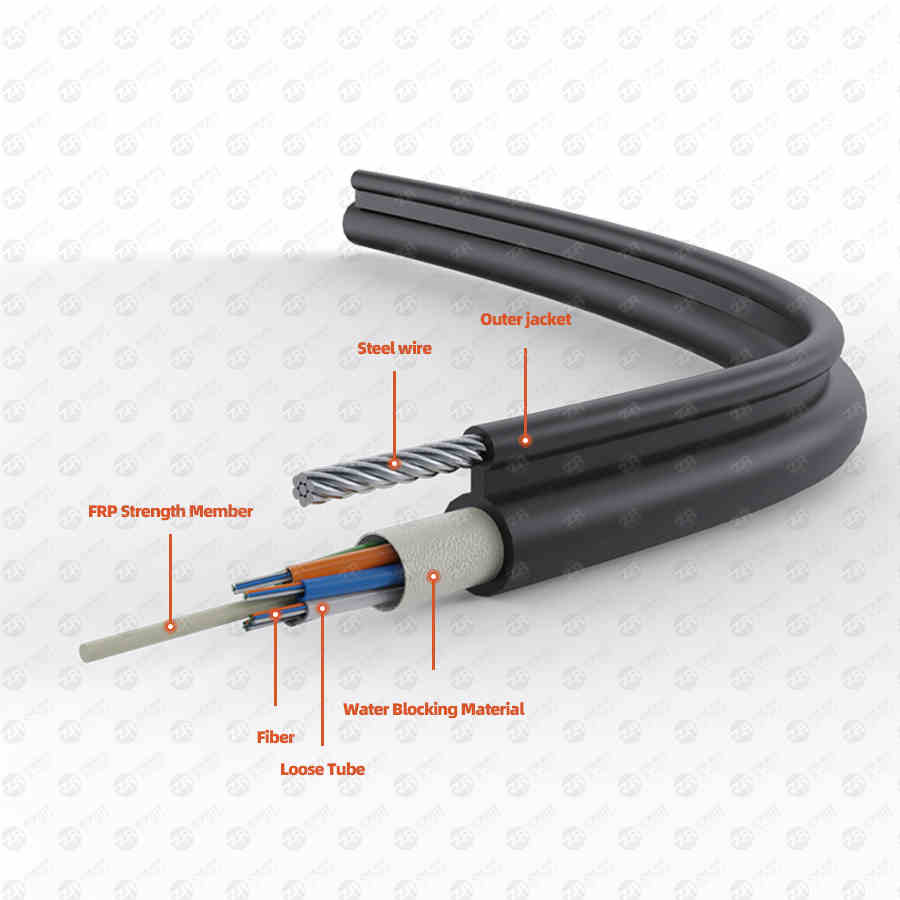
22. What is the main composition of the optical cable?
Answer: It is mainly composed of: fiber core, optical fiber ointment, sheath material, PBT (polybutylene terephthalate) and other materials.
23. What does the armor of the optical cable refer to?
Answer: It refers to the protective element (usually steel wire or steel tape) used in special-purpose optical cables (such as submarine optical cables, etc.). The armor is attached to the inner jacket of the cable.
24. What material is used for the cable sheath?
Answer: The optical cable sheath or sheath is usually composed of polyethylene (PE) and polyvinyl chloride (PVC) materials, and its function is to protect the cable core from external influences.
25. List special optical cables used in power systems.
A: There are mainly three kinds of special optical cables:
Ground wire composite optical cable (OPGW), the optical fiber is placed in the power line of the steel clad aluminum stranded structure. The application of OPGW optical cable plays the dual function of ground wire and communication, and effectively improves the utilization rate of power towers.
Wrap-around fiber optic cable (GWWOP), which is wrapped or suspended from the ground wire where there is an existing transmission line.
Self-supporting optical cable (ADSS) has strong tensile capacity and can be directly hung between two power poles and towers, and its maximum span can reach 1000m.
26. What are the application structures of OPGW optical cables?
Answer: There are mainly: 1) the structure of plastic tube layer twist + aluminum tube; 2) the structure of central plastic tube + aluminum tube; 3) aluminum skeleton structure; 4) spiral aluminum tube structure; 5) single-layer stainless steel tube structure (center Stainless steel tube structure, stainless steel tube layered structure); 6) Composite stainless steel tube structure (central stainless steel tube structure, stainless steel tube layered structure).
27. What is the main composition of the stranded wire outside the core of the OPGW optical cable?
Answer: It is composed of AA wire (aluminum alloy wire) and AS wire (aluminum clad steel wire).
28. To choose the OPGW optical cable model, what are the technical conditions that should be met?
Answer: 1) Nominal tensile strength (RTS) of OPGW cable (kN); 2) Number of fiber cores of OPGW cable (SM); 3) Short circuit current (kA); 4) Short circuit time (s); 5) Temperature Range (°C).
29. How is the bending degree of the optical cable limited?
Answer: The bending radius of the optical cable should not be less than 20 times the outer diameter of the optical cable, and not less than 30 times the outer diameter of the optical cable during the construction process (non-stationary state).
30. What should be paid attention to in ADSS optical cable project?
Answer: There are three key technologies: optical cable mechanical design, determination of suspension points and selection and installation of supporting hardware.
31. What are the main types of optical cable fittings?
Answer: Optical cable fittings refer to the hardware used to install optical cables, mainly including: tension clamps, suspension clamps, vibration isolators, etc.
32. Optical fiber connectors have two basic performance parameters, what are they?
Answer: Optical fiber connectors are commonly known as live joints. For the optical performance requirements of single-fiber connectors, the focus is on the two most basic performance parameters, insertion loss and return loss.
33. How many types of fiber optic connectors are commonly used?
Answer: According to different classification methods, fiber optic connectors can be divided into different types. According to different transmission media, they can be divided into single-mode fiber optic connectors and multi-mode fiber optic connectors; according to different structures, they can be divided into FC, SC, ST. , D4, DIN, Biconic, MU, LC, MT and other types; according to the pin end face of the connector can be divided into FC, PC (UPC) and APC. Commonly used fiber optic connectors: FC/PC fiber optic connectors, SC fiber optic connectors, and LC fiber optic connectors.
34. In the optical fiber communication system, the following items are common, please indicate their names.
AFC, FC type adapter ST type adapter SC type adapter FC/APC, FC/PC type connector SC type connector ST type connector LC type jumper MU type jumper Single-mode or multi-mode jumper
35. What is the insertion loss (or insertion loss) of a fiber optic connector?
Answer: It refers to the magnitude of the reduction of the effective power of the transmission line caused by the intervention of the connector. For the user, the smaller the value, the better. ITU-T stipulates that its value should not be greater than 0.5dB.
36. What is the return loss (or reflection attenuation, return loss, return loss) of a fiber optic connector? Answer: It is a measure of the input power component reflected back from the connector and returned along the input channel. Its typical value should be Not less than 25dB.
37. What is the most prominent difference between light emitting diodes and semiconductor lasers?
Answer: The light generated by the LED is incoherent light with a wide spectrum; the light generated by the laser is coherent light with a narrow spectrum.
38. What is the most obvious difference between the working characteristics of light-emitting diodes (LEDs) and semiconductor lasers (LDs)? Answer: LEDs do not have a threshold, while LDs have a threshold. Only when the injection current exceeds the threshold will laser be generated.
39. What are the two commonly used single longitudinal mode semiconductor lasers?
Answer: DFB lasers and DBR lasers are both distributed feedback lasers, and their optical feedback is provided by distributed feedback Bragg gratings in the optical cavity.
40. What are the two main types of light receiving devices?
Answer: There are mainly photodiodes (PIN tubes) and avalanche photodiodes (APDs).
41. What are the factors that cause the noise of the optical fiber communication system?
Answer: There are noises caused by unqualified extinction ratio, noise caused by random variation of light intensity, noise caused by time jitter, point noise and thermal noise of receiver, mode noise of optical fiber, noise caused by pulse broadening caused by chromatic dispersion, and noise caused by LD. Mode partition noise, noise due to frequency chirp of the LD, and noise due to reflections.
42. What are the main optical fibers currently used for transmission network construction? What are their main characteristics?
Answer: There are three main types, namely G.652 conventional single-mode fiber, G.653 dispersion-shifted single-mode fiber and G.655 non-zero dispersion-shifted fiber.
The dispersion of G.652 single-mode fiber in the C-band 1530-1565nm and L-band 1565-1625nm is relatively large, generally 17-22psnm·km. When the system rate reaches 2.5Gbit/s or more, dispersion compensation is required. At 10Gbit/s When the system dispersion compensation cost is relatively large, it is the most common type of optical fiber laid in the transmission network at present.
The dispersion of G.653 dispersion-shifted fiber in the C-band and L-band is generally -1 to 3.5psnm·km, and it is zero dispersion at 1550nm. The system rate can reach 20Gbit/s and 40Gbit/s, which is a single-wavelength ultra-long distance transmission. Best fiber. However, due to its zero dispersion characteristics, when using DWDM for capacity expansion, nonlinear effects will occur, resulting in signal crosstalk, resulting in four-wave mixing FWM, so DWDM is not suitable.
G.655 non-zero dispersion-shifted fiber: The dispersion of G.655 non-zero dispersion-shifted fiber in the C-band is 1-6 psnm·km, and the dispersion in the L-band is generally 6-10 psnm·km. The dispersion is small and avoids zero dispersion. The dispersion region not only suppresses the four-wave mixing FWM, it can be used for DWDM capacity expansion, and it can also enable high-speed systems. The new G.655 fiber can expand the effective area to 1.5 to 2 times that of the general fiber, and the large effective area can reduce the power density and reduce the nonlinear effect of the fiber.
43. What is the nonlinearity of optical fiber?
Answer: It means that when the optical power of the incoming fiber exceeds a certain value, the refractive index of the optical fiber will be nonlinearly related to the optical power, and Raman scattering and Brillouin scattering will occur, which will change the frequency of the incident light.
44. What effect will fiber nonlinearity have on transmission?
A: Non-linear effects will cause some additional losses and disturbances, degrading the performance of the system. WDM systems have high optical power and travel long distances along the fiber, thus producing nonlinear distortion. There are two types of nonlinear distortion: stimulated scattering and nonlinear refraction. Among them, stimulated scattering includes Raman scattering and Brillouin scattering. The above two kinds of scattering reduce the energy of incident light and cause loss. It can be ignored when the input fiber power is small.
45. What is PON (Passive Optical Network)?
Answer: PON is an optical fiber loop optical network in the local user access network, based on passive optical devices, such as couplers and optical splitters
Various causes of fiber attenuation
1. The main factors that cause optical fiber attenuation are: intrinsic, bending, extrusion, impurities, non-uniformity and docking.
Intrinsic: It is the inherent loss of the fiber, including: Rayleigh scattering, intrinsic absorption, etc.
Bending: When the fiber is bent, part of the light in the fiber will be lost due to scattering, resulting in loss.
Squeeze: Loss caused by tiny bends in an optical fiber when it is squeezed.
Impurities: Losses caused by impurities in the fiber absorbing and scattering light propagating in the fiber.
Non-uniformity: Loss caused by non-uniform refractive index of the fiber material.
Docking: The loss generated when the optical fiber is docked, such as: different axes (the coaxiality of single-mode fiber is required to be less than 0.8μm), the end face is not perpendicular to the axis, the end face is not flat, the butt core diameter does not match and the welding quality is poor.
When light enters from one end of an optical fiber and exits from the other end, the intensity of the light decreases. This means that after the optical signal propagates through the fiber, the light energy is partially attenuated. This means that there is some substance in the fiber or for some reason that blocks the passage of the light signal. This is the transmission loss of the fiber. Only by reducing the fiber loss can the optical signal be made unimpeded.
2. Classification of fiber loss
Optical fiber loss can be roughly divided into the inherent loss of the optical fiber and the additional loss caused by the operating conditions after the optical fiber is made. The specific breakdown is as follows:
Fiber loss can be divided into inherent loss and additional loss.
Inherent losses include scattering losses, absorption losses, and losses due to imperfect fiber structure.
Additional losses include microbending losses, bending losses and splice losses.
Among them, the additional loss is artificially caused during the laying process of the optical fiber. In practical applications, it is inevitable to connect the optical fibers one by one, and the optical fiber connection will produce loss. The slight bending, extrusion, and tensile force of the optical fiber will also cause loss. These are losses caused by the conditions of use of the fiber. The main reason for this is that under these conditions, the transmission mode in the fiber core changes. Additional losses can be avoided as much as possible. Below, we only discuss the inherent loss of fiber.
Among the inherent losses, scattering loss and absorption loss are determined by the characteristics of the fiber material itself, and the inherent loss caused by different operating wavelengths is also different. It is very important to understand the mechanism of loss and quantitatively analyze the loss caused by various factors for the development of low-loss optical fiber and the rational use of optical fiber.
3. Absorption loss of materials
Optical fibers are made of materials that absorb light energy. After the particles in the fiber material absorb the light energy, they vibrate and generate heat, and dissipate the energy, thus resulting in absorption loss. We know that matter is composed of atoms and molecules, and atoms are composed of nuclei and extranuclear electrons. The electrons revolve around the nucleus in a certain orbit. This is just like the earth where we live and the planets such as Venus and Mars all revolve around the sun. Each electron has a certain energy and is in a certain orbit, or each orbit has a certain energy level.
Orbitals closer to the nucleus have lower energy levels, and orbitals farther from the nucleus have higher energy levels. The magnitude of this energy level difference between orbitals is called the energy level difference. When an electron transitions from a low energy level to a high energy level, it absorbs the energy of the corresponding level of energy difference.
In an optical fiber, when electrons of a certain energy level are irradiated with light of a wavelength corresponding to the energy level difference, electrons located in the orbits of lower energy levels will transition to orbits of higher energy levels. This electron absorbs light energy, resulting in light absorption loss.
The basic material for making optical fibers, silicon dioxide (SiO2), itself absorbs light, one is called ultraviolet absorption, and the other is called infrared absorption. At present, optical fiber communication generally only works in the wavelength region of 0.8 to 1.6 μm, so we only discuss the loss in this working region.
The absorption peak generated by electronic transition in quartz glass is about 0.1-0.2 μm wavelength in the ultraviolet region. As the wavelength increases, its absorption gradually decreases, but the affected area is wide, up to wavelengths above 1 μm. However, UV absorption has little effect on silica fibers operating in the infrared region. For example, in the visible light region with a wavelength of 0.6μm, the ultraviolet absorption can reach 1dB/km, and at a wavelength of 0.8μm, it drops to 0.2-0.3dB/km, and at a wavelength of 1.2μm, it is only about 0.1dB/km.
The infrared absorption loss of silica fiber is caused by the molecular vibration of the material in the infrared region. There are several vibration absorption peaks above 2μm.
Due to the influence of various doping elements in the fiber, it is impossible for the silica fiber to have a low-loss window in the wavelength band above 2 μm, and the theoretical limit loss at the wavelength of 1.85 μm is 1dB/km.
Through research, it is also found that there are some "destructive molecules" in the quartz glass, mainly some harmful transition metal impurities, such as copper, iron, chromium, manganese and so on. Under the irradiation of light, these "bad guys" greedily absorb light energy and jump around, causing the loss of light energy. Removing "trouble molecules" and chemically purifying the material from which the fiber is made can greatly reduce losses.
Another absorption source in silica fiber is the study of hydroxide (OHˉ) phase. It was found that hydroxide has three absorption peaks in the optical fiber working band, which are 0.95μm, 1.24μm and 1.38μm, of which the wavelength of 1.38μm The absorption loss is the most serious and has the greatest impact on the fiber. At the wavelength of 1.38 μm, the absorption peak loss generated by the hydroxyl radical with a content of only 0.0001 is as high as 33 dB/km.
Where do these hydroxides come from? There are many sources of hydroxides. First, there are moisture and hydroxides in the materials for making optical fibers. These hydroxides are not easy to be removed during the purification process of the raw materials, and they are still used as hydrogen in the end. The form of oxygen radicals remains in the optical fiber; the second is that the hydroxide used to manufacture the optical fiber contains a small amount of moisture; the third is that water is generated due to chemical reactions during the manufacturing process of the optical fiber; the fourth is that the entry of outside air brings water vapor. However, the manufacturing process has now advanced to such a high level that the hydroxide content has been reduced to a level low enough that its effect on the fiber is negligible.
4. Scattering loss
In the dark night, you can see a beam of light by shining a flashlight into the air. Large beams of light from searchlights have also been seen in the night sky.
So, why do we see these beams of light? This is because there are many tiny particles such as smoke and dust floating in the atmosphere, and the light irradiates on these particles, which scatters and shoots in all directions. This phenomenon was first discovered by Rayleigh, so people named this kind of scattering "Rayleigh scattering".
How does scattering occur? The tiny particles such as molecules, atoms, and electrons that make up matter vibrate at certain natural frequencies, and can emit light with wavelengths corresponding to the vibrational frequencies. The vibration frequency of a particle is determined by the size of the particle. The larger the particle, the lower the vibrational frequency, and the longer the wavelength of the light emitted; the smaller the particle, the higher the vibrational frequency, and the shorter the wavelength of the emitted light. This vibrational frequency is called the natural vibrational frequency of the particle. But this vibration is not self-generated, it requires a certain amount of energy. Resonance occurs when a particle is exposed to light of a certain wavelength at the same frequency as the particle's natural vibration. The electrons in the particle start to vibrate at this vibrational frequency. As a result, the particle scatters light in all directions, the energy of the incident light is absorbed and converted into the energy of the particle, and the particle re-emits the energy in the form of light energy. Therefore, for those who observe from the outside, what they see is that the light hits the particles and scatters in all directions.
There is also Rayleigh scattering in the fiber, and the resulting optical loss is called Rayleigh scattering loss. Given the current level of fiber manufacturing technology, it can be said that Rayleigh scattering loss is unavoidable. However, since the size of the Rayleigh scattering loss is inversely proportional to the fourth power of the light wavelength, when the optical fiber operates in the long wavelength region, the influence of the Rayleigh scattering loss can be greatly reduced.
5. Congenital insufficiency, love can't help
The fiber structure is imperfect, such as air bubbles, impurities, or uneven thickness in the fiber, especially the core-cladding interface is not smooth, etc. When the light reaches these places, part of the light will be scattered in all directions, causing loss . This loss can be overcome, that is, to improve the fiber manufacturing process. Scattering makes the light radiate in all directions, and a part of the scattered light is reflected back in the opposite direction to the propagation of the fiber, and this part of the scattered light can be received at the incident end of the fiber. The scattering of light causes a portion of the light energy to be lost, which is undesirable. However, this phenomenon can also be used for us, because if we analyze the intensity of the received light at the transmitting end, we can check the breakpoint, defect and loss of the fiber. In this way, through human ingenuity, bad things are turned into good things.
Optical fiber loss In recent years, optical fiber communication has been widely used in many fields. To realize optical fiber communication, an important issue is to reduce the loss of optical fiber as much as possible. The so-called loss refers to the attenuation per unit length of the fiber, and the unit is dB/km. The level of optical fiber loss directly affects the transmission distance or the distance between repeater stations. Therefore, it is of great practical significance to understand and reduce the loss of optical fiber for optical fiber communication.
1. Absorption loss of fiber
This is caused by the absorption of light energy by fiber materials and impurities. They consume light energy in the form of heat energy in the fiber, which is an important loss in fiber loss. The absorption loss includes the following:
1. Substance intrinsic absorption loss This is the loss caused by the intrinsic absorption of the substance. It has two frequency bands, one is in the 8-12 μm region of the near-infrared, and the intrinsic absorption of this band is due to vibration. The intrinsic absorption band of another substance is in the ultraviolet band. When the absorption is very strong, its tail will be dragged to the 0.7-1.1 μm band.
2. Absorption loss caused by dopants and impurity ions Optical fiber materials contain transition metals such as iron, copper, chromium, etc., which have their own absorption peaks and absorption bands and vary with their valence states. The fiber loss caused by the absorption of transition metal ions depends on their concentration. In addition, the presence of OH- also produces absorption loss, the basic absorption peak of OH- is around 2.7 μm, and the absorption band is in the range of 0.5-1.0 μm. For pure silica fiber, the effect of loss caused by impurities can be ignored.
3. Atomic defect absorption loss The fiber material will be excited to produce atomic defects due to heat or strong radiation, resulting in light absorption and loss, but generally this effect is small.
2. Optical fiber scattering loss
The scattering inside the fiber will reduce the transmitted power and cause loss. The most important of scattering is Rayleigh scattering, which is caused by changes in density and composition inside the fiber material.
During the heating process of the optical fiber material, due to the thermal disturbance, the compressibility of the atoms is not uniform, the density of the material is not uniform, and the refractive index is not uniform. This inhomogeneity is fixed during the cooling process, and its size is smaller than the wavelength of light. When light encounters these non-uniform substances with random fluctuations smaller than the wavelength of the light wave during transmission, it changes the transmission direction, produces scattering, and causes loss. In addition, the uneven concentration of oxides contained in the optical fiber and uneven doping can also cause scattering and loss.
3. Waveguide scattering loss
This is scattering due to random distortion or roughness at the interface, and it is actually mode switching or mode coupling caused by surface distortion or roughness. One mode will give rise to other modes of transmission and radiation due to the fluctuation of the interface. Due to the different attenuation of various modes transmitted in the fiber, in the process of long-distance mode conversion, the mode with small attenuation becomes the mode with large attenuation. After continuous transformation and inverse transformation, although the loss of each mode will be balanced, but The mode generally produces additional loss, that is, additional loss due to mode conversion, and this additional loss is the waveguide scattering loss. To reduce this loss, it is necessary to improve the optical fiber manufacturing process. For well-drawn or high-quality fibers, this loss is essentially negligible.
Fourth, the radiation loss caused by fiber bending
Optical fibers are flexible and can be bent, but after bending to a certain extent, although optical fibers can guide light, the transmission path of light will change. The transmission mode is converted into a radiation mode, so that a part of the light energy penetrates into the cladding or passes through the cladding as a radiation mode that leaks out and is lost, resulting in loss. When the bending radius is greater than 5-10cm, the loss caused by bending can be ignored.
The order of the chromatographic arrangement in the optical fiber fusion system is as follows:
Blue;Orange;Green;Brown;Grey;White;Red;Black;Yellow;Purple;Pink;Blue;
The order of the bundle tubes in the optical cable is as follows:
One: When the multi-core fiber in the optical cable is divided into multiple bundles, the order of its arrangement is generally green, red and white bundles are as follows:
The green bundle tube is the first tube;
The second tube of the white bundle tube next to the green bundle tube:
The bundle tube that is exposed to the white bundle tube (the second tube) is the third tube;
Sequential rate push...
The red bundle tube is the last tube.
Two: In the case of multi-core fibers in the optical cable, there will also be a single bundle tube and then bundled with different colored ropes to distinguish the sequence of each bundle. The chromatogram is as follows:
blue; orange; green; brown;
gray; white; red; black;
yellow; purple; pink; this;
The first bundle is tied with blue silk rope;
The orange silk rope is the second bundle;
green......
Three: Whether the optical fibers are in the bundle tube or in the wire rope, their chromatographic arrangement is according to: blue; orange; green; brown; gray; white; red; black; yellow; purple; pink; this; one tube and one bundle Both are up to 12.
There are also manufacturers who use the two chromatograms in a clockwise direction: white 1, white 2, white 3, etc.
