
Indoor and outdoor optical fiber laying technical requirements
Usually in the integrated wiring, we will encounter the laying of indoor and outdoor optical fibers, and the indoor and outdoor optical cables are mainly used in the laying of horizontal subsystems and vertical backbone subsystems. So, what are the technical requirements for indoor and outdoor optical fiber laying in weak current projects?
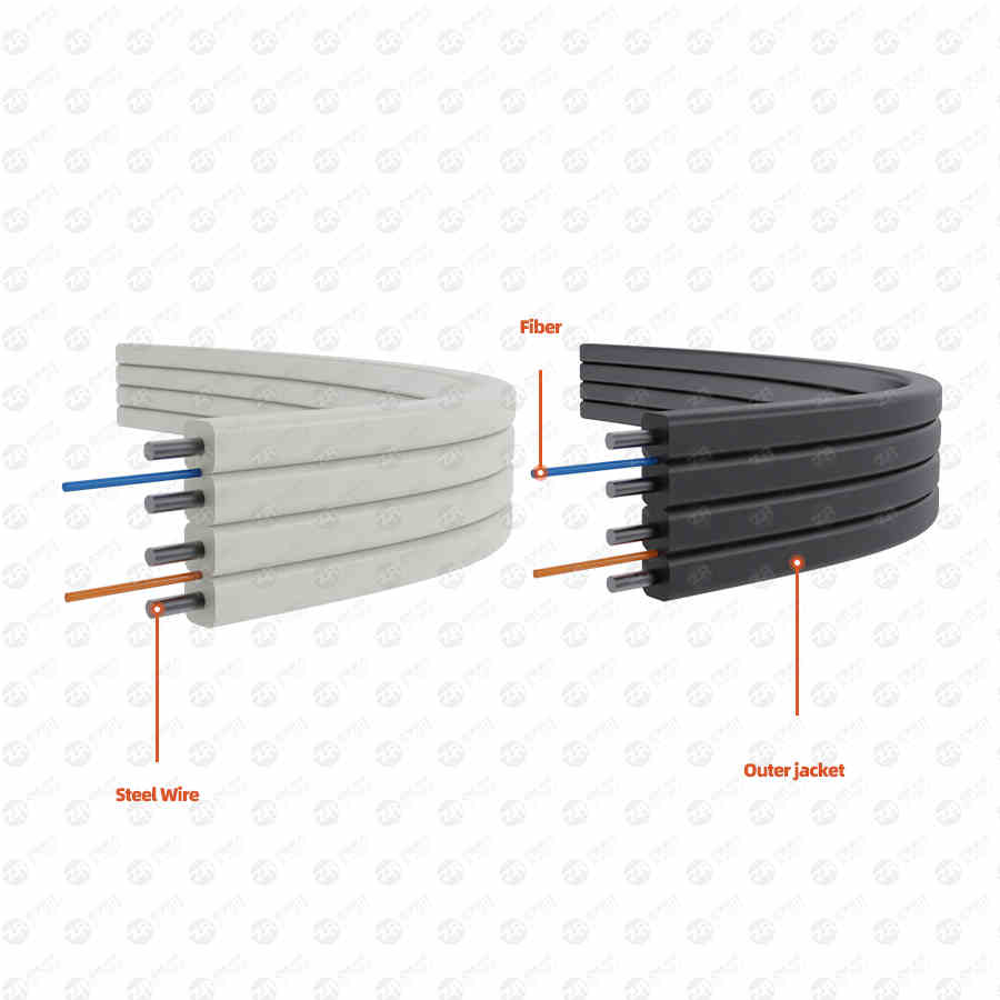
What are the technical requirements for indoor and outdoor optical fiber laying in weak current projects
Laying of indoor optical fibers
In order to prevent sagging or slipping, the optical cable must be firmly fixed on the upper, lower and middle of the channel of each floor. Usually, nylon cable ties or steel clips can be used for effective fixing.
Finally, linoleum plugging materials are also used to block and seal all the grooves and the gaps of the pipe holes through which the optical cables pass through each floor in the building, and fire prevention measures such as plugging fire-proof materials should be taken to achieve the effect of moisture-proof and fire-proof.
When laying the optical cable, an appropriate length should be reserved according to the design requirements. Generally, 5m-10m should be reserved at the equipment end, and it should be appropriately extended if there are special requirements.
Laying of outdoor optical fibers
The laying of outdoor optical fibers is divided into the laying of pipeline optical cables and the laying of direct buried optical cables.
Weak current engineering outdoor optical fiber
Laying of pipeline optical cable
1. Clean and test.
Before laying the optical cable, the pipe holes should be cleaned and tested one by one. When cleaning, use a special cleaning tool, and use a test stick for test pass inspection after cleaning. The inner diameter of the plastic sub-tube should be 1.5 times the outer diameter of the optical cable. When more than two sub-pipes are placed in a cement pipe hole, the equivalent total outer diameter of the sub-pipes should be less than 85% of the inner diameter of the pipe hole.
2. Lay out the plastic tube.
When wearing more than two plastic sub-pipes, if the pipes are of different colors, the ends may not be marked. If the pipes are the same color or no color, they should be marked separately at their ends.
3. Optical cable traction.
The length of one-time traction of the optical cable should generally be less than 1000m. When this distance is exceeded, segment traction should be adopted or auxiliary traction should be added in the middle position to reduce cable tension and improve construction efficiency.
In order to protect the surface of the optical cable from damage during the pulling process, when the optical cable penetrates the pipe hole, the pipe bend or intersects with other obstacles, protective measures such as guiding device or bell mouth protection tube should be adopted.
4. Reserve the margin.
After the optical cable is laid, the optical cable should be placed on the specified pallet one by one in the manhole or hand hole, and an appropriate margin should be left to prevent the optical cable from being too tight. When the optical cable in the manhole or hand hole needs to be connected, the reserved length should meet the minimum value specified in the table.
5. Joint processing.
The optical cable shall not have a joint in the pipe hole in the middle of the pipe. When the optical cable does not have a connector in the manhole, the optical cable is required to be bent and placed on the optical cable support plate for fixing and binding, and must not pass directly in the middle of the manhole, otherwise it will not only affect the construction and maintenance, but also easily lead to damage to the optical cable. When the optical cable has joints, it should be protected by pipes such as snake-shaped hoses or soft plastic pipes, and placed on the pallet to be fixed and bound.
6. Blocking and marking.
The outlet end of the pipe hole through which the optical cable is placed should be tightly sealed to prevent moisture or debris from entering the pipe. Optical cables and their splices should have identification marks, and indicate the serial number, type and specification of the optical cable. Antifreeze measures should also be taken in severe cold areas to prevent the optical cable from being damaged by freezing. In case the optical cable may be damaged by collision, insulating plates can be installed on or around it for partition protection.
Laying of direct buried optical cable
1. Buried depth.
Since the direct buried optical cable is directly buried under the ground, it must have a certain distance from the ground. With the help of the ground tension, the optical cable is not damaged. At the same time, it should also be ensured that the optical cable is not damaged by freezing.
2. Cleaning and backfilling of optical cable trenches.
The bottom of the ditch should be flat and free of debris such as gravel and hard clods that hinder the laying of optical cables. If the trench is stony or semi-stony, 10cm thick fine soil or sand should be laid at the bottom of the ditch and leveled. After the optical cable is laid, 30cm thick fine soil or sand should be backfilled as a protective layer. It is strictly forbidden to mix gravel, bricks, hard soil blocks, etc. into the protective soil layer. The protective layer should be gently stepped on manually.
3. Optical cable laying.
When laying optical cables or cables in the same trench, they should be pulled and laid separately at the same time. If it is laid in the same trench as the direct buried cable, the cable should be laid first, and then the optical cable should be laid in parallel at the bottom of the trench. Just like laying optical cables in trenches, they should be laid separately at the same time, and should not be crossed or overlapped at the bottom of the trench. The optical cable should be laid flat at the bottom of the trench or bent naturally to release the stress of the optical cable. If it is bent or arched, try to lay it flat, but it is absolutely not allowed to use strong methods such as stepping on the foot.
4. Identify.
Marks should be set up at the joints, turning points, reserved lengths, or intersections with other pipelines of directly buried optical cables for future maintenance. The sign can either use an autocratic sign, or borrow a permanent building near the optical cable, measure the distance between a certain part of the building and the optical cable, and record it for future reference.
What are the common problems in the process of laying optical fibers
First of all, during the use of the optical fiber fusion splicer, when the optical fiber is automatically calibrated, an optical fiber keeps moving up and down, and the screen display stops at "calibration". At this point we need to press the "Reset" button to reset the system.
Then, check whether the position deviation of the fiber end face in the Y/Z direction is less than 0.5 mm. If it is less than 0.5 mm, perform the following operations. Otherwise, send it to the factory for repair or check whether the bare fiber is clean. If it is not clean, deal with it; then clean the V-shaped groove. deposited dust. Finally, tap the small indenter with your finger to determine if the small indenter is compacting the fiber, and if not, deal with it. to try again.
Secondly, when the optical fiber fusion splicer performs discharge connection, the discharge program (1-5) set by the factory is not available, and the overall size is too large or too small. This is due to electrode aging, changes in the relative position of the fiber and the arc, or large changes in the operating environment. are handled as follows:
1. The condition of electrode aging. Check whether the electrode tip is damaged, if not, perform the "clean electrode" operation. If the tip of the electrode is damaged, refer to <Maintenance and Repair> to replace the electrode.
2. The relative position of the optical fiber and the arc changes. Enter the "Maintenance Mode" menu, press "Arc Position", and open the windshield to observe the relative position of the optical fiber and the arc. If the optical fiber is not in the middle of the electricity, you can perform the "clean electrode" operation several times, and then observe whether the relative position of the optical fiber and the arc changes. If it does not change, it is a stable position.
3. The operating environment has changed a lot. The treatment process is as follows: a. Carry out the discharge experiment until the "moderate discharge current" is carried out for three to five consecutive times. b. Enter the discharge parameter menu and check the discharge current value. c. The overall translation current (pre-melting current, welding current, repair current), so that the "welding current" value is "138 (0.1mA)". d. Press the "Parameter" key to return to the first-level menu state. e. Take the current translation amount in 3>, and modify the value of the "current deviation" item in the opposite direction. f. After confirmation, you can press the "OK" key to save. g. Press the "Parameter" key to exit the menu state.
In addition, when multimode fiber is spliced, bubbles always appear during the discharge process. In this case, it is mainly due to the large refractive index of the core of the multimode fiber. The specific processing process is as follows:
First, use the factory-set multi-mode discharge program as a template (that is, set the value of the "discharge program" item to less than "5", and confirm.
Second, carry out the discharge experiment until the "moderate discharge current" occurs three times.
Third, carry out multi-mode fiber splicing, and if bubbles still appear, modify the discharge parameters. The modification process is as follows: a. Enter the discharge parameter menu. b. The "premelting time" value is tentatively increased in steps of 0.1s. c. When connecting the optical fiber, if there are still bubbles, continue to increase the "pre-melting time" value until there is no bubbles during the connection (provided that the quality of the fiber end face meets the requirements). d. If the splicing process does not bubble and the fiber becomes thinner, the "pre-melting current" needs to be reduced.
The above is the whole content of the technical requirements for the indoor and outdoor optical fiber laying of the weak current project. In fact, the laying of the optical cable of the horizontal subsystem is very similar to that of the twisted pair, but because the tensile performance of the optical cable is worse, you should be more careful when pulling , the radius of curvature is also larger. The vertical backbone subsystem optical cable is used to connect the equipment room to the wiring room on each floor, and is generally installed in the cable shaft or the rising room.
