
What is the knowledge of the insertion loss of fiber optic connectors
As we all know, optical fiber connectors are widely used in optical fiber transmission lines, optical fiber distribution frames, optical fiber testing instruments and meters. So, do you know what are the key points of knowledge about the insertion loss of optical fiber connectors? Let's go and understand together.
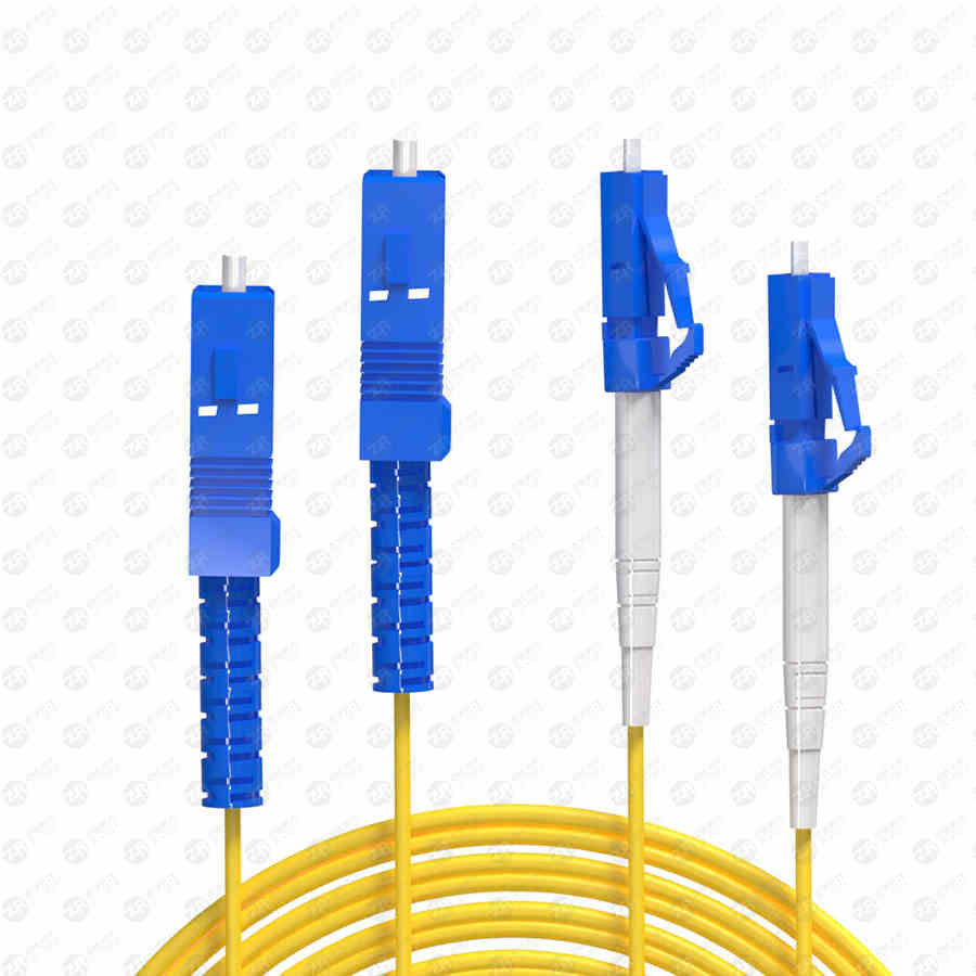
The optical fiber connector
1. The concept of insertion loss
(1) Definition of insertion loss (IL) of optical fiber connectors: where P1 is the output optical power, and P0 is the input optical power. Insertion loss is in dB.
(2) Test method for insertion loss of optical fiber connectors
There are generally three test methods for the insertion loss of optical fiber connectors: the benchmark method, the substitution method, and the standard jumper comparison method. Because of the high volume production process, testing for insertion loss must be fast, accurate and non-destructive. Therefore, most manufacturers now use the third method, that is, the standard jumper comparison method.
When the single-mode fiber pigtail is less than 50M and the multi-mode fiber pigtail is less than 10M, the loss of the pigtail itself can be ignored. The measured data at this time is the insertion loss of the three ends relative to the standard connector, and this data available to customers. When the single-mode fiber pigtail is larger than 50M and the multi-mode fiber pigtail is larger than 10M, the loss value of the fiber itself should be subtracted from the measured loss value.
(3) Repeatability
Repeatability refers to the variation range of the insertion loss of the same pair of plugs after multiple insertions and removals in the same adapter. The unit is expressed in dB. Repeatability should generally be less than 0.1dB.
(4) Interchangeability
Since the insertion loss of the optical fiber connector is measured by the standard jumper comparison method, its value is a relative value. Therefore, during any docking, the actual insertion loss value is likely to be greater than the value measured by the standard jumper comparison method, and different connectors and different adapters will have different degrees of influence. Therefore, there is an indicator requirement of interchangeability. Connector interchangeability refers to the variation range of insertion loss between different plugs or after arbitrary conversion of different adapters. It should generally be less than 0.2dB.
2. The main factors of the insertion loss of fiber optic connectors
(1) Loss caused by mismatch of optical fiber structural parameters (different core diameters, different numerical apertures, different refractive index distributions, and other reasons).
(2) Core alignment error (core misalignment loss)
The loss due to the lateral dislocation of the fiber core is called dislocation loss. It is an important cause of insertion loss.
where d, a, and w are the lateral dislocation, the core radius and the mode field diameter, respectively.
The dislocation loss of the multimode graded fiber in the steady state distribution of modes is:
When a single-mode fiber is connected, when the mode field distribution is approximated by a Gaussian, the dislocation loss is:
Such losses are caused by a number of factors. It mainly includes the core/cladding concentricity of the optical fiber, the concentricity of the ferrule, and the parameters of the test adapter are not ideal. The influence of the above factors on the insertion loss is also related to the external device.
(3) Loss caused by end face shape and gap
The main reason for this loss is that the physical parameters of the end face of the optical fiber connector are not ideal, resulting in non-planar direct contact between the two connecting optical fiber end faces, leaving a certain gap or non-planar contact. According to the relevant formula, it is concluded that as long as the end face gap is controlled within 1um, this loss can be ignored.
Of course, there are many other factors that affect the insertion loss besides the above three, such as: size matching of external devices, end face inclination, Fresnel reflection of the end face, etc.
3. Elements of production process control
(1) The quality of the ferrule
Mainly the inner diameter and concentricity of the ferrule. For multi-mode optical fiber connectors, the concentricity of the ferrule is required to be less than 3um, and for single-mode optical fiber connectors, the concentricity of the ferrule is required to be less than 1um. Factors such as the concentricity of the ferrule, the physical parameters of the polished rear face, and the matching size of the outer parts will ultimately affect the core/ferrule concentricity, which will eventually lead to the occurrence of dislocation loss.
(2) The level of grinding
The standard for measuring the quality of grinding depends on its end face and its physical parameters. There are three main physical parameters: curvature radius, spherical eccentricity, and fiber sag. For APC-type connectors, it also includes two parameters: end face angle (slope 8 degrees) and key angle deviation. These parameters can affect insertion loss. IEC has put forward clear requirements for these parameters, and has specific index provisions. To do this, a grinder with stable performance is essential. Most of the quality problems in the production process of optical fiber connectors are directly or indirectly related to the stability of the grinding machine.
Losses are caused by many factors. It mainly includes the core/cladding concentricity of the optical fiber, the concentricity of the ferrule, and the parameters of the test adapter are not ideal. The influence of the above factors on the insertion loss is also related to the size matching of the external devices, the loss caused by the shape of the end face and the gap. The main reason for this loss is that the physical parameters of the end face of the optical fiber connector are not ideal, resulting in non-planar direct contact between the two connecting optical fiber end faces, leaving a certain gap or non-planar contact. According to the relevant formula, it is concluded that as long as the end face gap is controlled within 1um, this loss can be ignored.
(3) Size matching of external parts
The dimensional fit of the outer parts will have a direct impact on the repeatability and interchangeability of the connector. Especially for APC type connectors, if the size matching is not ideal, its interchangeability and repeatability may exceed 0.1dB or worse.
4. Test control elements
(1) Accurate and reliable test equipment
In order to make the test data accurate and reliable, accurate and stable test instruments will provide a reliable guarantee for this.
(2) Standard connector
A standard connector is a set of precision-manufactured or selected connectors that include standard jumpers and standard adapters. The insertion loss of the optical fiber connector is actually its loss relative to the standard test line, so the indicators (optical parameters and physical parameters) of the standard test line must be strictly controlled. Similarly, the indicators of the adapter should be strictly controlled according to the principle of selecting standard adapters. In this way, the test results will best reflect the true quality of the tested connectors. Therefore, the key to reflect the accuracy and reliability of the test is the control of standard test lines and standard adapters.
(3) End face cleanliness
Because the outer diameter of the optical fiber is only 125um, and the light-passing part is smaller, the single-mode fiber is only about 9um, and the multi-mode fiber is 50um and 62.5um, so the cleanliness of the fiber end face is very high. Be sure to clean the fiber end face before testing to ensure that the end face is highly clean, so as to ensure accurate and reliable test results. If one cleaning is not enough, you can clean it several times.
5. Repeatability and interchangeability
(1) Factors affecting repeatability
Mainly the mechanical fit size. If the matching size is good, the same docking state can be reproduced every time it is plugged and unplugged, and the test results will not change greatly. In addition, the quality of the adapter will also affect the repeatability.
(2) Factors Affecting Interchangeability
All the factors in the third part, that is, the quality of the ferrule, the level of grinding, and the matching size of the outer parts will affect the interchangeability, so the importance of these indicators is even more highlighted.
The above is the whole content of the knowledge about the insertion loss of optical fiber connectors. Optical fiber connectors have excellent performance and outstanding functions. Its application scope will not only realize the connection of optical fibers. I believe that in the near future, the stage of optical fiber connectors will be will be wider.
