
Polarity of MPO/MTP Optical Links
Whether it is applied to the local area network of the enterprise or the backbone network of the data center, it is now developing in the direction of high-density wiring, so as to ensure the demand for broadband supply and high-density network connection. MPO/MTP multi-core cables are produced to meet high-density wiring.
Especially in the process of migrating 10G network to 40G/100G network, many network engineers will take MPO/MTP trunk cable as the preferred solution. But to ensure the accuracy of the polarity in the MPO/MTP network system, the design of the polarity of the MPO/MTP optical cable is very special. Let's discuss how to properly maintain the polarity of MPO/MTP.
What is polarity? Generally, an optical link requires two fibers to complete the entire transmission process. For example, an optical module includes a receiving end and a transmitting end. When using it, it must be ensured that the receiving end and the transmitting end are in an interconnected state, and the matching between the transmitting end (TX) and the receiving end (Rx) at both ends of the fiber link is determined by called polarity. In the traditional wiring system, people usually use connectors such as LC and SC, which can be easily matched, so there is no problem of polarity maintenance. However, for pre-terminated, high-density cabling systems, such as MPO/MTP connection systems, the issue of polarity must be taken seriously.
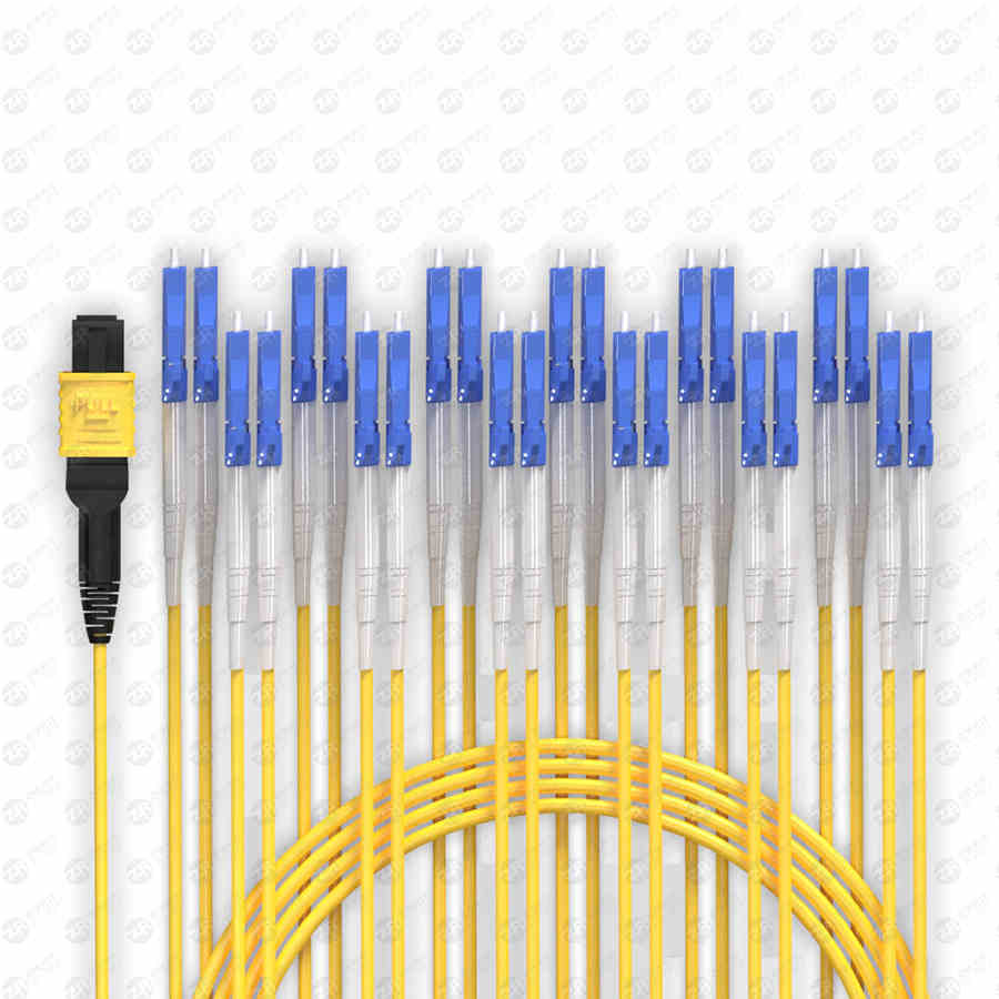
Before discussing the maintenance of MPO/MTP polarity, let's first get to know the MPO/MTP connector. The MPO connector is a multi-core multi-channel plug-in connector, which consists of a pair of MT sleeves, two guide pins, two shells and an adapter. Its standard feature is to use a standard diameter of 6.4mm x The guide void and guide pin of the 2.5mm rectangular ferrule end face are positioned and centered.
MPO connectors can be used for the connection of 2-12-core side-by-side optical fibers, and can be used for simultaneous connection of up to two rows of 24-core fibers. When docking, a spring installed at the end of the ferrule exerts an axial pressure on the ferrule until the outer frame sleeve of the connector is locked with the adapter. There is a male (convex) key on the upper side of the ferrule, which is used to limit the relative position between the connectors when connecting, so as to determine the correct docking sequence of the optical fibers. In addition, MPO connectors are divided into male and female headers. The connector interface is made of a female plug with a guide pin hole and a male plug with a guide pin butt and locked in an adapter. Because of its small size, high precision and high density, it is widely used in high-density and high-speed data centers.
MPO/MTP optical link
The three polarity methods specified in the TIA568 standard are called Method A, Method B, and Method C. In order to meet the TIA568 standard, MPO trunk cables are also divided into three types: straight-through, complete crossover and pair crossover, namely, Type A (key up - key down straight-through), Type B (key up - key up/key down-key down complete cross), Type C (key up - key down line pair cross). The three MPO trunk cables and the three polarity methods are described in detail below.
Straight-through MPO trunk optical cable: Straight-through MPO trunk optical cable uses straight-through cable. The two ends are pre-terminated with MPO connectors with keyway up and MPO connectors with keyway down. Therefore, the corresponding positions of the optical fibers at both ends of the optical cable are the same, that is, It is said that the position of the first core hole of the left connector corresponds to the position of the first core hole of the right connector.
Complete crossover MPO trunk cable: The complete crossover MPO trunk cable uses a reversed cable, and both ends are pre-terminated with MPO connectors with the keyway facing up. In this cable, the corresponding positions of the fibers at both ends of the cable are opposite. That is to say, the position of the first core hole of the left connector corresponds to the position of the 12th core hole of the right connector.
Wire-to-cross MPO trunk cable: The wire-to-cross MPO trunk cable is the same as the straight-through MPO trunk cable. The MPO connectors with the keyway up and the MPO connector with the keyway down are pre-terminated at both ends. However, the wire-to-cross MPO trunk is In the optical cable, the corresponding positions of the two adjacent optical fibers at one end of the optical cable are opposite to the corresponding positions of the two adjacent optical fibers at the other end, that is to say, the position of the first core hole of the left connector corresponds to the position of the second core hole of the right connector. , and the position of the second core hole of the left connector corresponds to the position of the first core hole of the right connector.
Different polarity methods use different kinds of MTP trunk cables. However, all methods utilize duplex patch cords to form fiber optic links. The TIA standard also defines two different types of LC or SC duplex fiber optic patch cords to complete end-to-end duplex connections: A-A (crossover) patch cords and A-B (straight-through) patch cords.
This section will explain how to ensure the correctness of the connection polarity of the MPO optical device under the TIA standard.
A-type connection mode: Tx means launch) reflects the A-type connection mode. Type A connection uses straight-through MPO trunk cables. In order to ensure the accuracy of polarity, two types of jumpers can be used: standard duplex A-B type jumpers are used on the left side of the fiber link, and A-A type jumpers are used on the right side. jumper.
Type B connection: The type B connection uses a fully crossed MPO trunk optical cable. Since the corresponding positions of the fibers at both ends of the fully crossed MPO trunk optical cable are opposite, both ends of the optical fiber link use standard A-B type jumpers.
Type C connection method: The type C connection method uses a pair of crossover MPO trunk optical cables, and both ends of the optical fiber link use standard A-B type jumpers.
The polarity problem faced by network engineers when using MPO/MTP products to meet the increasing demand for high-speed transmission can be solved by selecting appropriate MPO optical cables, MPO connectors, and MPO transfer module boxes and jumpers. For a reliable high-density 40/100G transmission solution, first select the desired polarity method, and then select the appropriate MPO/MTP optical components to support this polarity method.
