
Basic knowledge of optical cable wiring and system design
As a high-bandwidth, high-security data transmission medium, optical fiber is widely used in various large and medium-sized networks. Due to the high cost of cables and equipment, optical fibers are mostly only used in the network backbone, that is, in the system wiring of vertical backbone subsystems and building group subsystems to realize the connection between buildings and floors. A horizontal wiring subsystem with high requirements for speed and security.
Optical cable routing
1. Optical fiber
1. Light and its characteristics:
1) Light is an electromagnetic wave
The wavelength range of visible light is: 390~760nm (nanometer). The part larger than 760nm is infrared light, and the part smaller than 390nm is ultraviolet light. The application of optical fiber is: 850, 1300, 1550 three kinds.
2) Refraction, reflection and total reflection of light.
Because the propagation speed of light in different substances is different, when light is emitted from one substance to another substance, refraction and reflection will occur at the interface of the two substances. Also, the angle of the refracted light varies with the angle of the incident light. When the angle of the incident light reaches or exceeds a certain angle, the refracted light will disappear, and all the incident light will be reflected back, which is the total reflection of light. Different substances have different refraction angles for light of the same wavelength (that is, different substances have different refractive indices of light), and the same substance has different refraction angles for light of different wavelengths. Optical fiber communication is formed based on the above principles.
2. Optical fiber structure and type:
1) Optical fiber structure:
The bare fiber is generally divided into three layers: the central high refractive index glass core (the core diameter is generally 50 or 62.5 μm), the middle is the low refractive index silica glass cladding (the diameter is generally 125 μm), and the outermost is the resin coating for reinforcement. Floor.
2) Numerical aperture:
The light incident on the end face of the fiber cannot be all transmitted by the fiber, only the incident light within a certain angle range can. This angle is called the numerical aperture of the fiber. A larger numerical aperture of the optical fiber is advantageous for the butt-joining of the optical fiber. Optical fibers produced by different manufacturers have different numerical apertures (AT&T??CORNING).
3) Types of optical fibers:
A. According to the transmission mode of light in the fiber, it can be divided into: single-mode fiber and multi-mode fiber.
Multimode fiber: The central glass core is thicker (50 or 62.5μm) and can transmit light in multiple modes. But its intermodal dispersion is large, which limits the frequency of transmitting digital signals, and it will be more serious with the increase of distance. For example: 600MB/KM fiber has only 300MB bandwidth at 2KM. Therefore, the distance of multimode fiber transmission is relatively short, generally only a few kilometers.
Single-mode fiber: The central glass core is relatively thin (the core diameter is generally 9 or 10 μm), and only one mode of light can be transmitted. Therefore, its intermodal dispersion is very small, which is suitable for long-distance communication, but its chromatic dispersion plays a major role, so the single-mode fiber has higher requirements on the spectral width and stability of the light source, that is, the spectral width should be narrower and the stability should be better. .
B. According to the optimal transmission frequency window: conventional single-mode fiber and dispersion-shifted single-mode fiber.
Conventional type: The optical fiber manufacturer optimizes the optical fiber transmission frequency on a single wavelength of light, such as 1300nm.
Dispersion-shifted type: Optical fiber manufacturers optimize the transmission frequency of optical fibers at two wavelengths of light, such as: 1300nm and 1550nm.
C. According to the distribution of refractive index, it is divided into: abrupt and graded fibers.
Abrupt type: The refractive index from the central core of the fiber to the glass cladding is abrupt. It has low cost and high intermodal dispersion. It is suitable for short-distance low-speed communication, such as industrial control. However, due to the small intermodal dispersion of single-mode fiber, the single-mode fiber adopts abrupt type.
Graded fiber: The refractive index from the center core of the fiber to the glass cladding is gradually reduced, so that the high-mode light can propagate in a sinusoidal form, which can reduce the dispersion between modes, improve the bandwidth of the fiber, and increase the transmission distance, but the cost is high. Mode fibers are mostly graded fibers.
4) Common fiber specifications:
Single mode: 8/125μm, 9/125μm, 10/125μm
Multimode: 50/125μm, European standard 62.5/125μm, American standard
Industrial, Medical and Low Speed Networks: 100/140μm, 200/230μm
Plastic: 98/1000μm for car control
3. Optical fiber manufacturing and attenuation:
1) Optical fiber manufacturing:
At present, optical fiber manufacturing methods mainly include: in-tube CVD (chemical vapor deposition) method, in-rod CVD method, PCVD (plasma chemical vapor deposition) method and VAD (axial vapor deposition) method.
2) Attenuation of fiber:
The main factors that cause fiber attenuation are: intrinsic, bending, extrusion, impurities, non-uniformity and butt joint.
Intrinsic: It is the inherent loss of the fiber, including: Rayleigh scattering, intrinsic absorption, etc.
Bending: When the fiber is bent, part of the light in the fiber will be lost due to scattering, resulting in loss.
Squeeze: Loss caused by tiny bends in an optical fiber when it is squeezed.
Impurities: Losses caused by impurities in the fiber absorbing and scattering light propagating in the fiber.
Non-uniformity: Loss caused by non-uniform refractive index of the fiber material.
Docking: The loss generated when the optical fiber is docked, such as: different axes (the coaxiality of single-mode fiber is required to be less than 0.8μm), the end face is not perpendicular to the axis, the end face is not flat, the butt core diameter does not match and the welding quality is poor.
4. The advantages of optical fiber:
1) The passband of the optical fiber is very wide. Theoretically, it can reach 3 billion megahertz.
2) The length of the non-relay section is tens to more than 100 kilometers, and the copper wire is only a few hundred meters.
3) Not affected by electromagnetic fields and electromagnetic radiation.
4) Light weight and small size. For example: 900 pairs of twisted-pair cables with 21,000 voice channels, the diameter is 3 inches, and the weight is 8 tons/KM. The optical fiber cable with ten times the communication capacity has a diameter of 0.5 inches and a weight of 450P/KM.
5) Optical fiber communication is not electrified, and can be used in flammable and violent places for safe use.
6) The use of a wide range of ambient temperature.
7) Chemical corrosion, long service life.
2. Optical cable
1. Manufacture of optical cable:
The manufacturing process of optical cable is generally divided into the following processes:
1) Screening of optical fibers: select optical fibers with excellent transmission characteristics and qualified tension.
2) Dyeing of optical fibers: use standard full chromatogram to identify, requiring high temperature not fading and not migrating.
3) Secondary extrusion: Use plastic with high elastic modulus and low linear expansion coefficient to extrude into a certain size tube, incorporate the optical fiber and fill it with moisture-proof and waterproof gel, and store it for a few days (not less than two days) .
4) Optical fiber cable twisting: twist several extruded optical fibers and strengthening units together.
5) Squeeze the outer sheath of the optical cable: add a layer of sheath to the twisted optical cable.
2. Types of optical cables:
1) According to the laying method, there are: self-supporting overhead optical cable, pipeline optical cable, armored buried optical cable and submarine optical cable.
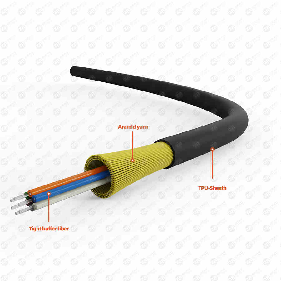
2) According to the optical cable structure, it is divided into: bundled optical cable, layered optical cable, tightly hugged optical cable, ribbon optical cable, non-metallic optical cable and branchable optical cable.
3) According to the use, it is divided into: optical cable for long-distance communication, short-distance outdoor optical cable, hybrid optical cable and optical cable for building.
3. Construction of optical cable:
Over the years, the construction of optical cables has enabled us to have a set of mature methods and experience.
Outdoor construction of optical cable:
The most important thing for long-distance cable laying is to choose a suitable path. The shortest path is not necessarily the best, but also pay attention to the right to use the land, the possibility of erection or burial, etc.
There must be very complete design and construction drawings for convenient and reliable construction and future inspections. During construction, be careful not to put the optical cable under heavy pressure or be punctured by hard objects.
When the optical cable turns, its turning radius is 20 times larger than the diameter of the optical cable itself.
1) Construction of outdoor aerial optical cable:
A. The overhead method of hanging wire brackets is simple and cheap, and is the most widely used in my country, but it is time-consuming to add hooks and arrange them.
B. Hanging wire winding overhead method, this method is more stable and less maintenance work. But a special wrapping machine is required.
C. The self-supporting overhead method has high requirements on the trunk line, difficult construction and maintenance, and high cost. It is rarely used in China at present.
D. When overhead, a guiding device must be installed at the place where the optical cable leads to the trunk, and the optical cable should not be dragged to the ground. Pay attention to reducing friction when pulling the optical cable. A length of fiber optic cable should be left on each trunk for expansion and contraction.
E. Pay attention to the reliable grounding of metal objects in the optical cable. Especially in mountainous areas, high-voltage power grid areas and many areas, there are generally 3 grounding points per kilometer, and even non-metallic optical cables are used.
2) Construction of outdoor pipeline optical cable:
A. Before construction, the occupancy of the pipeline should be checked, the plastic sub-pipes should be cleaned and placed, and the traction line should be placed at the same time.
B. Calculate the deployment length, and there must be enough reserved length.
C. The length of one laying should not be too long (generally 2KM). When wiring, it should be pulled from the middle to both sides.
D. The traction force of the cable is generally not more than 120kg, and the reinforcing core part of the optical cable should be pulled, and the waterproof and strengthening treatment of the head of the optical cable should be done.
E. The lead-in and lead-out of the optical cable must be equipped with a follow-up device, and the floor cannot be directly mopped.
F. The pipeline optical cable should also pay attention to reliable grounding.
3)The laying of directly buried optical cables:
A. The depth of direct buried optical cable trench should be excavated according to the standard. The standard is shown in the following table:
B. Where trenches cannot be dug, the pipelines can be laid overhead or drilled.
C. The bottom of the ditch should be flat and firm, and a part of sand, cement or support can be pre-filled if necessary.
D. Manual or mechanical traction can be used when laying, but attention should be paid to guidance and lubrication.
E. After the laying is completed, the soil should be covered and compacted as soon as possible.
4) Laying of optical cables in buildings:
A. When laying vertically, special attention should be paid to the load-bearing problem of the optical cable. Generally, the optical cable should be fixed once every two layers.
B. When the optical cable passes through the wall or floor, a protective plastic pipe with a mouth guard should be added, and the pipe should be filled with flame retardant filler.
C. A certain amount of plastic pipes can also be laid in advance in the building, and when the optical cable is to be laid in the future, the optical cable can be laid by traction or vacuum method.
4. Selection of optical cable:
The selection of optical cables is not only based on the number of optical fibers and the type of optical fibers, but also the outer sheath of the optical cable according to the use environment of the optical cable.
1) When the outdoor optical cable is directly buried, the armored optical cable should be selected. When overhead, an optical cable with a black plastic outer sheath with two or more reinforcing ribs can be used.
2) When selecting optical cables used in buildings, attention should be paid to their flame retardant, poisonous and smoke characteristics. Generally, the flame-retardant but smoke-bearing type (Plenum) can be used in the pipeline or forced ventilation, and the flame-retardant, non-toxic and smoke-free type (Riser) should be used in the exposed environment.
3) When cabling vertically in the building, distribution cables can be used; when wiring horizontally, breakout cables can be used.
4) If the transmission distance is less than 2km, you can choose multi-mode optical cable. If it exceeds 2km, you can use repeater or choose single-mode optical cable.
3. Connection and detection
1. Optical cable connection:
The methods mainly include permanent connection, emergency connection and active connection.
1) Permanent fiber optic connection (also called hot melt):
This type of connection is to use the method of electric discharge to melt and connect the connection points of the optical fibers together. Generally used in long-distance connection, permanent or semi-permanent fixed connection. Its main feature is that the connection attenuation is the lowest among all connection methods, with a typical value of 0.01~0.03dB/point. However, when connecting, special equipment (fusion machine) and professionals are required to operate, and the connection point also needs to be protected by a special container.
2) Emergency connection (also called) cold melting:
The emergency connection mainly uses mechanical and chemical methods to fix and bond the two optical fibers together. The main feature of this method is that the connection is fast and reliable, and the typical attenuation of the connection is 0.1~0.3dB/point. However, the long-term use of the connection point will be unstable, and the attenuation will increase greatly, so it can only be used for emergency use in a short time.
3) Active connections:
Active connection is a method of connecting site to site or site to fiber optic cable using various fiber optic connection devices (plugs and sockets). This method is flexible, simple, convenient and reliable, and is mostly used in computer network wiring in buildings. Its typical attenuation is 1dB/connector.
2. Optical fiber detection:
The main purpose of optical fiber inspection is to ensure the quality of system connection, reduce fault factors and find out the fault point of optical fiber. There are many detection methods, mainly divided into manual simple measurement and precision instrument measurement.
1) Manual and simple measurement:
This method is generally used to quickly detect the on-off of optical fibers and to distinguish the fibers made during construction. It uses a simple light source to inject visible light from one end of the optical fiber, and observe which one emits light from the other end. Although this method is simple, it cannot quantitatively measure fiber attenuation and fiber breakpoints.
2) Precision instrument measurement:
Using an optical power meter or an optical time domain reflectometry (OTDR) to quantitatively measure the optical fiber, the attenuation of the optical fiber and the attenuation of the joint can be measured, and even the position of the breakpoint of the optical fiber can be measured. This measurement can be used to quantitatively analyze the causes of fiber optic network failures and evaluate fiber optic network products.
Fourth, the application and system design of optical fiber
1. Application of optical fiber:
Human society has now developed into an information society, and the exchange of information such as voice, image and data is very large. The previous means of communication can no longer meet the current requirements, and optical fiber communication has been widely used due to its advantages of large information capacity, good confidentiality, light weight, small size, and long distance without hops. Its application fields cover communication, transportation, industry, medical, education, aerospace and computer industries, and are developing to a wider and deeper level. The application of light and optical fiber is bringing profound influence and change to human life.
2. Optical fiber network system design:
The design of an optical fiber system generally follows the following steps:
1) First of all, find out what kind of network is to be designed, what is its current situation, and why fiber optics are used.
2) According to the actual situation, select the appropriate optical fiber network equipment, optical cables, jumpers and other items for connection. Selection should be based on availability, and then based on performance, price, service, origin and brand.
3) Determine the route of the line according to the customer's requirements and network type, and draw the wiring diagram.
4) When the route is long, the attenuation margin of the system needs to be calculated. The calculation can be carried out according to the following formula:
Attenuation margin = transmitting optical power - receiving sensitivity - line attenuation - connection attenuation (dB) where line attenuation = cable length × unit attenuation;
The unit attenuation has a lot to do with the quality of the fiber, generally single mode is 0.4~0.5dB/km; multimode is 2~4dB/km.
Connection attenuation includes welding attenuation joint attenuation. Welding attenuation is related to welding methods and the quality of personnel. Generally, hot melting is 0.01~0.3dB/point; cold melting is 0.1~0.3dB/point; joint attenuation has a great relationship with the quality of the joint. Usually 1dB/point. The system attenuation margin is generally not less than 4dB.
5) If the calculation is unqualified, the design should be modified according to the situation, and then calculated. This situation may sometimes repeat several times.
3. Design example:
Transformation of a campus network:
According to the situation, a three-port repeater (twisted pair-optical fiber-slim cable) is used on one side of the existing thin cable network, and a twisted pair HUB with optical fiber backbone is used on the other side. In the middle, an overhead or buried 4-core outdoor multimode optical fiber cable of bundled tube type is used, and then it is spliced into an indoor jumper with ST head (because the optical fiber interface of the equipment is ST type).
Attenuation calculation: (Generally, multi-mode equipment does not need to be calculated within 2km, here is just an example)
Transmit power: -16dBm
Receive sensitivity: -29.5dBm
Line attenuation: 1.5km×3.5dB/km=5.25dB
Connection attenuation: The attenuation of 2 connectors is: 2 points × 1dB/point = 2dB
The two points of welding are: 2 points×0.07dB/point=0.14dB
Attenuation margin=-16dBm-(-29.5dBm)-5.25dB-0.14dB-2dB=6.11(dB
After the above calculation, it can be seen that the system capacity is greater than 4dB, and the above options can meet the requirements.
