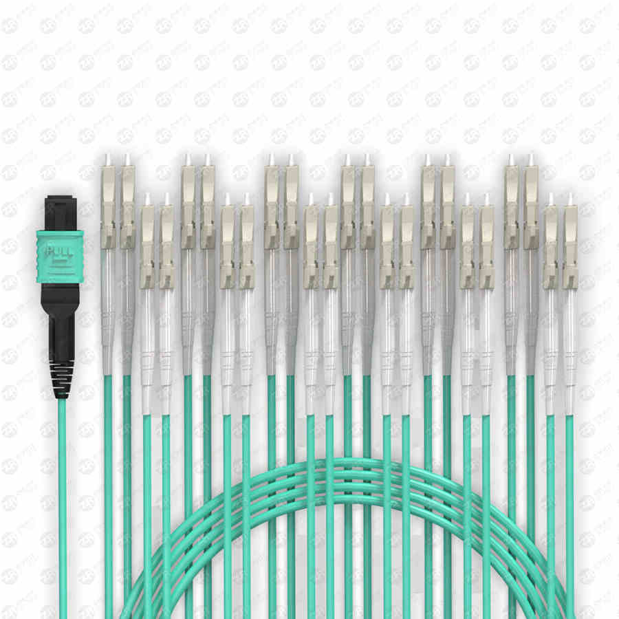
Gigabit single-mode fiber module testing
The transmission of the optical fiber module on the optical cable is completed by a pair of OXAs on the optical fiber module. That is, the optical fiber transmitter (TOXA) and the optical fiber receiver (ROXA) are completed. So, how to test the gigabit single-mode fiber module?
Gigabit single-mode fiber module
TOSA is designed to have the maximum transmitted optical power, and ROXA also has a certain optical signal sensitivity receiving range in design. In particular, the signal receiving range of the ROXA is certain. If the signal is too small, it cannot be detected. If the signal is too high, the ROXA will be saturated with light and the device will fail without damage.
Since LX, ZX, XD fiber optic modules are specially designed for long-distance optical cable transmission, the transmit power of the transmitter is much higher than that of multimode modules, especially XD, ZX, and EX are more prominent. Therefore, the connection test of single-mode fiber is different from that of multi-mode modules.
When single-mode fiber optic modules use jumpers for short-distance (local) testing, they must be properly completed by adding a large enough attenuator to the fiber optic line.

The general attenuator requirements are as follows:
1000LX (10-15KM): 5dm
1000XD (40-50KM): 15dm
1000ZX (70-80KM): 28DB
1000EX (100-120KM): 45db
Without using the attenuator test, unless the optical module manufacturer has designed the receiving sensitivity automatic adjustment function for the receiving power of the module, otherwise, the phenomenon of receiving light saturation or critical saturation of the receiver may occur.
In the case of light-saturated light reception at the receiver, the outside of the optical fiber link will show a connection failure; while in the case of critical light-reception saturation, there will be gross packets in data transmission.
The occurrence of the above two situations often makes users mistakenly believe that the optical fiber module is faulty, and these two situations are also applicable to the situation where the optical cable insertion failure is too small and the received optical signal exceeds the receiving range of the ROXA in the actual optical cable and optical fiber matching use. .
In the ideal case without considering dispersion, the allowable transmission distance of a gigabit fiber optic module can be obtained by the following formula:
Transmission distance=(TOSA minimum transmit power-ROSA minimum receive power)/(0.25 to 0.35DBM), where 0.25 to 0.35dbm is the insertion loss of each KM optical cable, depending on the quality of the optical cable.
Another direct calculation method of transmission distance:
Module transmission distance=(TOSA minimum transmit power-ROSA minimum receive power) absolute value-optical cable insertion attenuation (dbm)
When choosing a suitable fiber optic module, it must be considered that the maximum receiving power of the optical signal at the receiving end should not exceed the maximum receiving sensitivity of ROSA!
If the optical line attenuator cannot be found at the test site, a simple and easy method is to pull out the jumper (SC/LC/ST/FC) of the inserted module a little until the device port link indicator lights up but not If it is turned off, then we can basically confirm that the optical signal received by ROXA is within the allowable receiving design range of the device.

