
Basic knowledge of optical fiber communication transmission
Advantages of optical fiber communication Large communication capacity, long relay distance, no electromagnetic interference, abundant resources, light weight and small size of optical fiber...
Optical fiber communication transmission
Advantages of Optical Fiber Communication
Large communication capacity
long relay distance
Free from electromagnetic interference
Abundant resources
Optical fiber is light in weight and small in size
A Brief History of Optical Communication Development
more than 2000 years ago
Beacon Tower - Lighting, Semaphore
1880
Optical phone - wireless optical communication
1970
Optical Fiber Communication
In 1966, the "father of optical fiber" Dr. Kao Kun first proposed the idea of optical fiber communication.
In 1970, Lin Yanxiong of the Bell Institute developed a semiconductor laser that can work continuously at room temperature.
In 1970, Corning's Kapron (Kapron) made a fiber with a loss of 20dB/km.
1977 Chicago's first 45Mb/s commercial line.
Because the propagation speed of light in different substances is different, when light is emitted from one substance to another substance, refraction and reflection will occur at the interface of the two substances. Also, the angle of the refracted light varies with the angle of the incident light. When the angle of the incident light reaches or exceeds a certain angle, the refracted light will disappear, and all the incident light will be reflected back, which is the total reflection of light. Different substances have different refraction angles for light of the same wavelength (that is, different substances have different refractive indices of light), and the same substance has different refraction angles for light of different wavelengths. Optical fiber communication is formed based on the above principles.
Reflectance distribution: An important parameter to characterize optical materials is the refractive index, which is represented by N. The ratio of the speed of light C in vacuum to the speed of light V in the material is the refractive index of the material.
N=C/V
The refractive index of silica glass for optical fiber communication is about 1.5
Fiber Structure
The bare fiber is generally divided into three layers:
The first layer: the central high refractive index glass core (the core diameter is generally 9-10μm, (single mode) 50 or 62.5 (multimode).
The second layer: the middle is a low-refractive-index silica glass cladding (generally 125 μm in diameter).
The third layer: the outermost is the resin coating for reinforcement.
1) Core: high refractive index, used to transmit light;
2) cladding coating: the refractive index is lower, forming a total reflection condition together with the core;
3) Protective jacket jacket: strong, can withstand greater impact, protect the optical fiber.
3mm fiber optic cable
Orange MM Multimode
Yellow SM Singlemode
Fiber size
The outer diameter is generally 125um (an average hair is 100um)
Inner diameter: single-mode 9um, multi-mode 50/62.5um
Numerical aperture
The light incident on the end face of the fiber cannot be all transmitted by the fiber, only the incident light within a certain angle range can. This angle is called the numerical aperture of the fiber. A larger numerical aperture of the optical fiber is advantageous for the butt-joining of the optical fiber. Optical fibers produced by different manufacturers have different numerical apertures
Types of optical fibers
According to the transmission mode of light in the fiber, it can be divided into:
Multi-Mode (abbreviation: MM)
Single-Mode (Single-Mode) (abbreviation: SM)
Multimode fiber: The central glass core is thicker (50 or 62.5μm) and can transmit light in multiple modes. But its intermodal dispersion is large, which limits the frequency of transmitting digital signals, and it will be more serious with the increase of distance. For example: 600MB/KM fiber has only 300MB bandwidth at 2KM. Therefore, the distance of multimode fiber transmission is relatively short, generally only a few kilometers.
Single-mode fiber: The central glass core is relatively thin (the core diameter is generally 9 or 10 μm), and only one mode of light can be transmitted. In fact, it is a kind of step-type fiber, but the core diameter is very small. In theory, only straight light from a single propagation path is allowed to enter the fiber and propagate in a straight line in the core. Fiber pulses are barely broadened. Therefore, its intermodal dispersion is very small, which is suitable for long-distance communication, but its chromatic dispersion plays a major role, so the single-mode fiber has higher requirements on the spectral width and stability of the light source, that is, the spectral width should be narrower and the stability should be better. .
Classification of optical fibers
By material:
Glass fiber: both the core and the cladding are glass, with low loss, long transmission distance and high cost;
Silicone optical fiber: the core is glass, the cladding is plastic, the characteristics are similar to those of glass fiber, and the cost is lower;
Plastic optical fiber: Both the core and the cladding are plastic, with large loss, short transmission distance and low price. It is mostly used for home appliances, audio, and short-distance image transmission.
According to the optimal transmission frequency window: conventional single-mode fiber and dispersion-shifted single-mode fiber.
Conventional type: The optical fiber manufacturer optimizes the transmission frequency of the optical fiber at a single wavelength of light, such as 1300nm.
Dispersion-shifted type: Optical fiber manufacturers optimize the transmission frequency of optical fibers at two wavelengths of light, such as: 1300nm and 1550nm.
Abrupt type: The refractive index from the central core of the fiber to the glass cladding is abrupt. It has low cost and high intermodal dispersion. It is suitable for short-distance low-speed communication, such as industrial control. However, due to the small intermodal dispersion of single-mode fiber, the single-mode fiber adopts abrupt type.
Gradient fiber: The refractive index from the center core of the fiber to the glass cladding gradually decreases, so that the high-mode light can propagate in a sinusoidal form, which can reduce the intermodal dispersion, improve the fiber bandwidth, and increase the transmission distance, but the cost is high. Mode fibers are mostly graded fibers.
Common Fiber Specifications
Fiber Size:
1) Single-mode fiber core diameter: 9/125μm, 10/125μm
2) Outer diameter of cladding (2D)=125μm
3) One coating outer diameter = 250μm
4) Pigtail: 300μm
5) Multimode:
50/125μm, European standard
62.5/125μm, US standard
6) Industrial, medical and low speed network: 100/140μm, 200/230μm
7) Plastic: 98/1000μm for car control
Fiber attenuation
The main factors that cause fiber attenuation are: intrinsic, bending, extrusion, impurities, non-uniformity and butt joint.
Intrinsic: It is the inherent loss of the fiber, including: Rayleigh scattering, intrinsic absorption, etc.
Bending: When the fiber is bent, part of the light in the fiber will be lost due to scattering, resulting in loss.
Squeeze: Loss caused by tiny bends in an optical fiber when it is squeezed.
Impurities: Losses caused by impurities in the fiber absorbing and scattering light propagating in the fiber.
Non-uniformity: Loss caused by non-uniform refractive index of the fiber material.
Docking: The loss generated when the optical fiber is docked, such as: different axes (the coaxiality of single-mode fiber is required to be less than 0.8μm), the end face is not perpendicular to the axis, the end face is not flat, the butt core diameter does not match and the welding quality is poor.
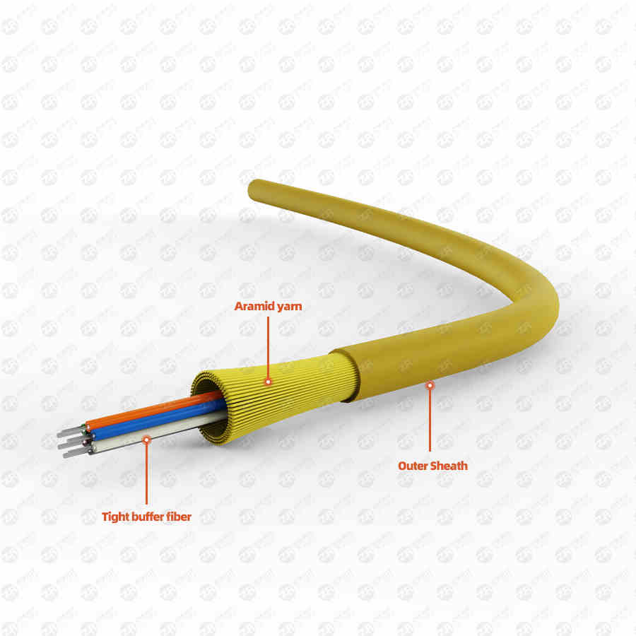
Types of fiber optic cables
1) According to the laying method, there are: self-supporting overhead optical cable, pipeline optical cable, armored buried optical cable and submarine optical cable.
2) According to the optical cable structure, it is divided into: bundled optical cable, layered optical cable, tightly hugged optical cable, ribbon optical cable, non-metallic optical cable and branchable optical cable.
3) According to the use, it is divided into: optical cable for long-distance communication, short-distance outdoor optical cable, hybrid optical cable and optical cable for building.
Fiber optic cable splicing and termination
The connection and termination of optical cables are the basic skills that the maintenance personnel of optical cable lines must master.
Cable connection technology classification:
1) The splicing technology of optical fiber and the splicing technology of optical cable are two parts.
2) The end of the optical cable is similar to the connection of the optical cable, but the operation should be different due to the different joint materials.
Types of fiber optic connections
Optical fiber splices can generally be divided into two categories:
1) Fixed splicing of optical fibers (commonly known as dead joints). Optical fiber fusion splicer is generally used; it is used for the direct head of optical cable.
2) The flexible connector of the optical fiber (commonly known as the live connector). Connect with a detachable connector (commonly known as a union). Used for fiber jumpers, equipment connections, etc.
Due to the incompleteness of the fiber end face and the uneven pressure of the fiber end face, the splice loss of the optical fiber spliced by one-time discharge is relatively large, and the secondary discharge fusion method is now used. First, preheat and discharge the fiber end face, shape the end face, remove dust and sundries, and at the same time make the fiber end face pressure uniform through preheating.
Monitoring method of optical fiber connection loss
There are three monitoring methods for fiber connection loss:
1. Monitor on the fusion splicer.
2. Monitoring of light source and optical power meter.
3. OTDR measurement method
How to operate fiber optic connection
Optical fiber splicing operations are generally divided into:
1. Processing of the fiber end face.
2. Optical fiber connection installation.
3. Fiber fusion.
4. Protection of fiber optic connectors.
5. There are five steps to leave the residual fiber.
Usually the connection of the entire optical cable is carried out according to the following steps:
The first step: a large number of good lengths, strip the optical cable, and remove the cable jacket;
Step 2: Clean and remove the oil filling paste in the optical cable.
Step 3: Bundle the optical fibers.
Step 4: Check the number of fiber cores, check the fiber number, and check whether the color code of the fiber is correct;
The fifth step: strengthen the heart connection;
Step 6: Connect various auxiliary wire pairs, including business wire pairs, control wire pairs, shielded ground wires, etc. (if there are the above wire pairs.
The seventh step: the connection of the optical fiber.
The eighth step: optical fiber connector protection processing;
The ninth step: the storage of the optical fiber residual fiber;
Step 10: Complete the connection of the optical cable sheath;
Step 11: Protection of optical cable connectors.
fiber loss
1310 nm : 0.35 ~ 0.5 dB/Km
1550 nm : 0.2 ~ 0.3dB/Km
850 nm : 2.3 ~ 3.4 dB/Km
Optical fiber splice point loss: 0.08dB/point
Fiber splicing point 1 point/2km
Common fiber nouns
1) Attenuation
Attenuation: energy loss when light is transmitted in the optical fiber
2) Dispersion
Dispersion: The widening of the bandwidth caused by a light pulse traveling a distance along an optical fiber. It is the main factor limiting the transfer rate.
Intermodal Dispersion: Occurs only in multimode fibers because different modes of light travel along different paths.
Material Dispersion: Light travels at different speeds at different wavelengths.
Waveguide Dispersion: Occurs because light energy travels at slightly different speeds as it travels through the core and cladding. In single-mode fiber, it is very important to change the dispersion of the fiber by changing the internal structure of the fiber.
Fiber Type
G.652 zero dispersion point is around 1300nm
G.653 zero dispersion point is around 1550nm
G.654 Negative Dispersion Fiber
G.655 Dispersion Shifted Fiber
full-wave fiber
3) Scattering
Due to the imperfect basic structure of light, the light energy loss is caused, and the light transmission no longer has good directionality at this time.
Fiber System Basics
The structure of the basic optical fiber system and its function introduction:
1. Transmitting unit: convert electrical signals into optical signals;
2. Transmission unit: the medium carrying the optical signal;
3. Receiver unit: receive optical signals and convert them into electrical signals;
4. Connecting devices: connecting optical fibers to light sources, light detection and other optical fibers.
coupler
The main function redistributes the optical signal
Important application in fiber optic networks
especially in local area networks
Application on wavelength division multiplexing devices
basic structure
Couplers are bidirectional passive devices
The basic forms are tree, star
——There is a splitter corresponding to the coupler
wavelength division multiplexer
WDM—Wavelength Division Multiplexer transmits multiple optical signals in one optical fiber, and these optical signals have different frequencies and different colors. The wavelength division multiplexer is to couple multiple optical signals into the same fiber; the demultiplexer is to distinguish multiple optical signals from one fiber.
Definition of pulse in digital system:
1. Amplitude: The height of the pulse represents the optical power energy in a fiber optic system.
2. Rise time: The time it takes for a pulse to rise from 10% to 90% of its maximum amplitude.
3. Fall Time: The time it takes for a pulse to fall from 90% to 10% of its amplitude.
4. Pulse width: the width of the pulse at 50% amplitude, expressed in time.
5. Cycle: The specific time of the pulse is the working time required to complete a cycle.
6. Extinction ratio: the ratio of 1 signal optical power to 0 signal optical power.
Definitions of commonly used units in optical fiber communication:
1. dB = 10 log10 ( Pout / Pin )
Pout: output power; Pin: input power
2. dBm = 10 log10 (P / 1mw)
is a widely used unit in communication engineering;
Usually expresses optical power with reference to 1 mW;
example: –10dBm means that the optical power is equal to 100uw.
3. dBu = 10 log10 (P / 1uw)
