
ADSS optical cable construction and precautions
1 ADSS cable overview
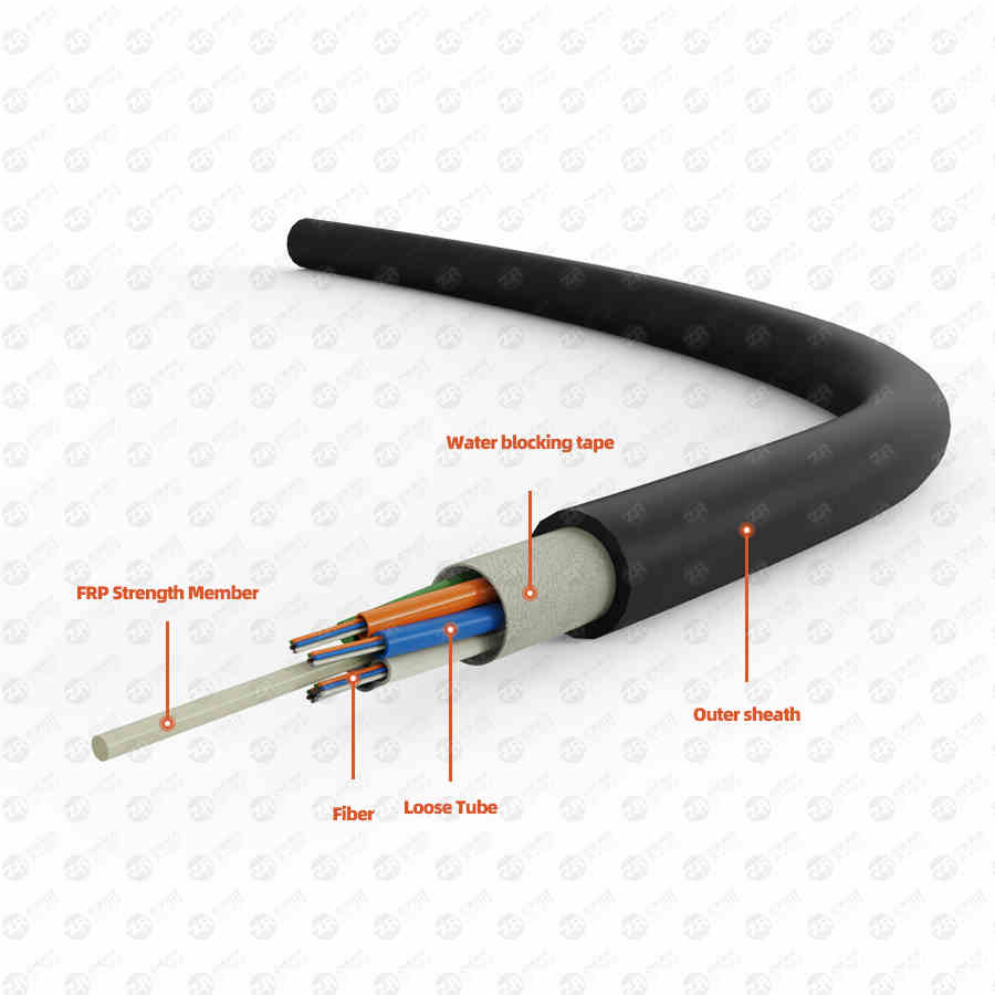
1.1 The structure of ADSS optical cable ADSS is the abbreviation of All Dielectric Self-Supporting aerial optical cable in English, which means "all-dielectric self-supporting optical cable", and its structure does not contain any metal materials. ADSS fiber optic cable structure is currently divided into two categories: layer stranding and central bundle tube.
1.2 Selection of optical cable hanging point Since the high-voltage induced electric field has strong electrical corrosion to the optical cable, the optical cable hanging point should be selected at a position with a small field strength: AT sheath ≤ 25KV/m, generally used for overhead power lines of 110 KV and above ;PE sheath <12KV/m, generally used for overhead power lines of 35KV and below.
The projection of the optical cable in both the horizontal and vertical directions should not cross the ground wire of the conductor. In order to avoid the collision (also known as whiplash) between the cable and the conductor and the ground wire when the wind deflects and creeps. In addition, the optical cable should not collide and rub against the tower.
When the above conditions are met, the force on the line tower is the smallest.
For the 220KV line, it is recommended to hang the optical fiber cable of the tensile tower on the first layer of the cross arm, at the first node in the direction of the side conductor. The double-loop optical cable is hung at the middle intersection of the first-layer cross-arm and the second-layer cross-arm. The cement door-type pole optical cable is hung under the cross arm of the pole and tower, and the position between 300mm-500mm above the cable hoop.
For 110KV lines, tension towers, portal poles, double-circuit iron towers or single poles of steel pipes, and single poles of cement, because there is no electric corrosion problem of electric field strength, the optical cable is recommended to be hung between 300mm-500mm under the cross arm of the first layer. Location. The corner door-type pole optical cable is hung between 1m and 1.5m on the first layer of the cross arm. The cat head tower optical cable is hung at the node position of the turning point of the cross arm.
For 35KV and 10KV lines, the optical cable can be hung under the cross arm, which is a more suitable position on the communication line.
ADSS optical cable construction
2 Basic technical requirements for the construction of ADSS optical cables
2.1 Safety distance for live line tower operation The location selection of the optical cable hanging point satisfies the safety distance requirement of "working on live line towers". (Minimum distance from live wire: 110KV≥1.5m, 220KV≥3.0m). According to the "Safety Regulations", the installation of ADSS optical cables on live lines can be regarded as work on live line towers. Therefore, the minimum distance between the operator's range of activities and the tools and materials they carry should not be less than the above-mentioned safe distance from the live wire (110KV is not less than 1.5 meters, 220KV is not less than 3.0 meters). Insulated non-polar ropes, insulated safety belts, and insulated tools must be used during construction. The wind power should not be greater than level 5, and special personnel should be set up to monitor them. If the above conditions cannot be met, construction should be carried out according to live work or power outage.
2.2 Tension and side pressure requirements during construction The glass fiber core in the ADSS optical cable is very easy to break, and will be damaged by stretching and side pressure. Therefore, the optical cable cannot be squeezed or stretched beyond the standard when the optical cable is installed. During construction, a tension pay-off machine should be used for tension pay-off, the traction tension should be stable, the traction tension should not exceed the index requirements, and the tension and lateral pressure during the erection of ADSS optical cables should not be too large (public account: power transmission and distribution lines).
2.3 Requirements for ADSS cable outer sheath
The flat and smooth surface of the outer sheath of the ADSS optical cable can effectively reduce electrical corrosion. If the outer sheath of the optical cable is worn, scratched, or ruptured, the optical cable will be corroded and damaged in a short time. , branches, houses, spanning racks, towers, cable tray edges and other objects friction and collision, can not use metal tools to scratch the optical cable.
2.4 Requirements for ADSS cable bending radius
There is a limit to the bending of ADSS optical cable. Exceeding the limit will cause damage. The bending radius index of the optical cable is as follows:
The bending radius of the optical cable during construction is ≥30D (D is the diameter of the optical cable)
The bending radius of the optical cable during operation is ≥20D (D is the diameter of the optical cable)
2.5 ADSS cable other requirements
The longitudinal twist of ADSS optical cable will cause damage, so non-polar insulated braided traction rope and anti-twist device must be used during construction.
The glass fiber core in the ADSS optical cable will be broken after being damp and water, so during construction, whether it is an opening test or after the construction, the end of the optical cable must be sealed with a waterproof tape.
The model, length, number of cores, span and matching hardware configuration of each reel of optical cable are different, and are produced according to the design of the design institute. Each cable has a uniform number, and each number corresponds to a certain base tower in a certain line. Therefore, the cables shall not be arbitrarily adjusted during construction. Optical cable fittings are designed and produced according to the diameter, tension and span of each optical cable, and cannot be replaced at will. The construction team must strictly follow the cable reel and hardware configuration table designed by the design institute to carry out the construction of optical cable exhibition.
There must be enough excess cable on the pole tower at the splice box of each reel of optical cables, and the length of the excess cable of the splice is ≥ the height of the optical cable hanging point from the ground + 25 meters. After the optical cable enters the equipment room, there must be enough excess cable. After the optical cable enters the equipment room and reaches the installation position, the length of the excess cable is ≥25 meters.
Under the premise of ensuring a safe distance, the installation height of the optical cable splice box and the remaining cable reel is ≥10M from the ground. When conditions permit, the installation position should be raised as much as possible.
3 Preparations before construction of ADSS optical cable
3.1 Personnel preparation 1. Personnel participating in the construction of optical cable racks must be trained in this technical specification and pass the examination.
2. Personnel working at heights, tractor drivers, surveyors and car drivers must have the qualification certificate for the professional examination.
3. The commander or the person in charge of the construction of each process of the erection construction must choose an experienced line technician.
Fourth, the optical cable rack facility organization is generally divided into safety supervision coordination group, preparation group, exhibition traction rope group, optical cable exhibition tension line group, the specific division of labor is as follows:
Tasks of the Safety Supervision Coordination Group:
1. Responsible for the organization and coordination of construction, safety and quality inspection.
2. Responsible for external coordination. Responsible for the logistics of contacting power outages, suspension of flights, crossing over, compensation for young crops, etc.
3. Assign an experienced safety technician to follow the pulling end of the optical cable, check the junctions, obstacles, crossings, sharp turns, etc. of the optical cable over the pulley along the way, and quickly stop the pulling at any time if any abnormality is found, and troubleshoot (public account: input distribution lines).
Tasks to prepare the group:
1. Clear line passage obstacles;
2. Inventory and transportation of optical cables and hardware materials;
3. Set up a spanning frame.
The task of laying out the traction rope group:
1. Responsible for the installation of the hoop clamp and the pay-off pulley of the tower to be erected for a reel of optical cables;
2. Spread the traction rope tower by tower and connect it with anti-twist connectors;
3. Use a portable winch or a motorized winch to lift the traction rope to a safe distance from the ground and then approach the anchor.
When the traction rope is lifted into the air, the working group must check whether there is any phenomenon of pulley jumping and non-rotation, whether the traction rope has friction, towers and obstacles, and whether there is a phenomenon of pulling up, and take remedial measures in time. If the pulley envelope angle is too small, a series pulley must be attached, and the tightening line group should be notified in time, because these faults will also occur during the pulling process of the optical cable.
4. If special terrain is found, the abnormal changes of the line must be reported to the person in charge of construction, and the person in charge of the safety supervision coordination group and the cable exhibition and tightening group shall be notified. And sent the left-behind personnel to monitor the pulling work of the optical cable, and immediately stopped pulling if any abnormal situation was found.
The tasks of the optical cable exhibition and tightening line group:
1. Responsible for the layout of traction field, tension field and cable reel;
2. Responsible for pulling optical cables and tightening cables;
3. Responsible for the installation of optical cable fittings.
4. Responsible for arranging the stretch field in the transition field, and preparing for the work of pulling the optical cable tomorrow.
3.2 Technical preparation 1. Before the erection construction, the technical preparations mainly include:
1. Carry out line investigation, focusing on the investigation of crossing over and obstacles.
2. To prepare technical measures for erection construction, including construction calculation.
3. Technical disclosure of the erection works.
2. The purpose of the line survey is to provide a basis for the preparation of erection technical measures. The main items are:
1. Traffic and terrain conditions along the route;
2. Obstacles in the line passage;
3. The situation of crossing and crossing along the line should include the owner of the object to be crossed and its on-site conditions, etc.;
3. The requirements for compiling "Technical Measures for Architectural Construction" are:
1. The preparation of technical measures for erection construction must be based on the design and construction drawings;
2. It should be written by technicians with experience in rack construction. The writer must participate in the on-site investigation, be familiar with the site conditions, and be familiar with the design drawings and documents.
3. The contents of the technical measures for the erection construction include: the relevant instructions for the erection construction; the observation method of the tightening line and the slack of the wire; the installation drawing of the fittings; the configuration table of the cable reel and the fittings; the detailed list of the tower; , site layout, tool configuration, operating requirements, quality standards and safety measures.
4. The slack value of the observation file in the tensile section should be calculated in the construction calculation of the erection.
5. The contents of making the pay-off work diagram include: tower gear number, gear distance, cross-over, etc. The focus is on the layout of the stretch field, the control value of the traction force and the tension.
4. After the preparation of "Technical Measures for Rack Construction", it can only be implemented after the approval of construction supervisors and factory supervisors and the approval of the production director (or chief engineer). Before construction, a comprehensive technical disclosure must be made to the construction workers.
3.3 Preparation of basic construction tools
1. Before erection, the equipment should be prepared. The main contents are:
1. According to the determined construction organization and construction method, prepare a list of machinery and tools.
2. Count on-site machines and tools according to the machine tool list, and supplement the shortage in time to ensure that the number of machines and tools meets the construction needs.
3. Clean up and inspect construction equipment. All equipment must be tested in accordance with the requirements of safety regulations to ensure that the quality of construction equipment is qualified, especially the insulation inspection of insulating traction ropes.
4. All mechanical equipment, such as tractor, tensioner, brake cable frame, motorized winch, etc., must be checked and maintained before construction. Make sure the device is in good condition.
5. The pay-off pulley must be inspected, repaired and maintained one by one to ensure that the components are complete and the rotation is flexible.
6. Communication tools must be checked one by one to ensure sufficient power.
7. The safety protection appliance should be managed by a special person, and the test should be carried out according to the regulations during use.
2. Each construction team must have the following basic construction equipment
1. A tensioner (or a pay-off frame with a braking force of not less than 1.3KN)
2. One tractor (3T)
3. 17 woven nylon traction ropes (Φ16*200m/piece)
4. 17 anti-twist connectors (1T)
5. 20 nylon pulleys (Φ400mm)
6. 6 nylon pulleys (Φ600mm)
7. 4 hand hoists (1.5T)
8. Wire rope sleeve
9. Silk rope (Φ12mm) 200 meters
10. 10 walkie-talkies (range 5KM)
