
Advantages and disadvantages of fiber optic transmission
First, the characteristics of optical fiber transmission
Optical cables are not easy to branch, because they transmit optical signals, so they are generally used for point-to-point connections. Experimental multipoint systems with optical bus topologies have been built, but are still too expensive. In principle, due to the small power loss and attenuation of optical fiber, there is a greater potential for bandwidth. Therefore, the number of connectors that can be supported by general optical fiber is much more than that of twisted pair or coaxial cable. The low-cost and reliable transmitter is a 0.85um wavelength light-emitting diode LED, which can support a transmission rate of 100Mbps and a local area network within the range of 1.5 to 2KM. Laser diode transmitters are expensive and cannot meet the million-hour lifetime requirement. The LED detector PIN operating at 0.85um wavelength is also a low-cost receiver.
The signal gain of the avalanche photodiode is larger than that of the PIN, but it needs a power supply of 20 to 50V, while the PIN detector only needs a 5V power supply. If you want to achieve a longer distance and a higher speed, you can use a 1.3um wavelength system, which has very little attenuation, but is more expensive than a 0.85um wavelength system. In addition, the matching optical fiber connectors are also very important, requiring each connector to have a connection loss of less than 25dB, easy installation and low price.
The larger the core and aperture of the fiber, the more light it receives from the light-emitting diode (LED), and the better its performance. Fibers with a core diameter of 100um and a cladding diameter of 140um provide fairly good performance. The received light energy is 4dB more than that of 62.5/125um fiber and 8.5dB more than that of 50/125um fiber. The attenuation of fiber running at 0.8um wavelength is 6dB/Km, and the attenuation of fiber running at 1.3um wavelength is 4dB/Km. The 0.8um fiber bandwidth is 150MHz/Km, and the 1.3um fiber bandwidth is 500MHz/Km.
In the integrated wiring system, it is very suitable and necessary to use optical fiber as the transmission medium for the main line.
Using a light wavelength division multiplexing technology WDM (WAVELENGTHDIVISIONMULTI-PLEXING), multiple bits can be multiplexed, sent, and transmitted on one line, generally transmitted in parallel by one byte and eight bits, using different wavelengths for each bit stream , so it requires support circuitry to operate at low speeds. The optical fiber link of WDM is suitable for the device interface of byte width and is a new data transmission system.
Second, the advantages and disadvantages of optical fiber transmission
advantage:
1. High sensitivity, no interference from electromagnetic noise.
2. Small size, light weight, long life and low price.
3. Insulation, high voltage resistance, high temperature resistance, corrosion resistance, suitable for work in special environments.
4. The geometric shape can be adjusted according to the environmental requirements, and the signal transmission is easy.
5. High bandwidth, large communication volume, low attenuation, and long transmission distance.
6. The signal crosstalk is small and the transmission quality is high.
7. High confidentiality.
8. It is easy to lay and transport raw materials.
shortcoming:
1. The texture is brittle and the mechanical strength is poor.
2. The cutting and splicing of optical fibers requires certain tools, equipment and techniques.
3. Materials for optical fiber transmission
The optical fiber used in the integrated wiring system is a glass multi-mode LED with a wavelength of 850nm, the transmission rate is 100Mbps, and the effective range is about 20Km. Its core and cladding are composed of two media with different optical properties. The inner medium has a higher index of refraction for light than the medium surrounding it. It can be known from physics that at the interface of two media, when light is incident from the side with high refractive index to the side with low refractive index, as long as the incident angle is greater than a critical value, a reflection phenomenon will occur, and the energy will not be affected. loss. At this time, the covering layer wrapped around the periphery acts like an opaque substance, preventing light from escaping from the surface during the interpenetration process.
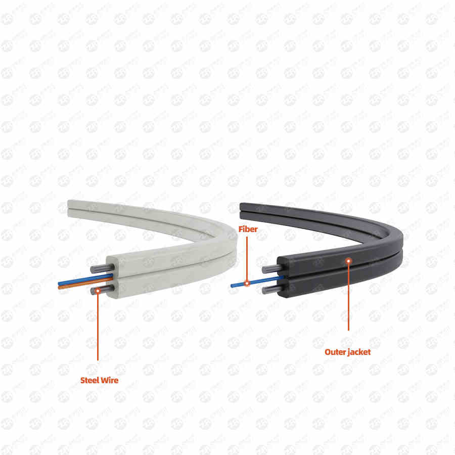
Fibers produced, whether in glass or plastic media, transmit the full visible light and part of the infrared spectrum. Optical cables made of optical fibers have various structural forms. There are two main types of optical cables for short distances:
A layer structure optical cable is to add steel wire or nylon wire in the center, there are several optical fibers in the outer bundle, and a layer of plastic sheath is added on the outside;
The other is a high-density optical cable, which is made of multiple layers of ribbons, and a row of optical fibers is laid in parallel on each layer of ribbons.
Fourth, the optical fiber transmission process
Optical fiber transmission is that the light-emitting diode LED or the injection laser diode ILD sends out the optical signal to propagate along the optical medium, and at the other end, there is a PIN or APD photodiode as a detector to receive the signal. The modulation of the optical carrier is the amplitude shift keying method, also known as the brightness modulation (IntensityModulaTIon). A typical approach is to represent two binary numbers with the appearance and disappearance of light at a given frequency. Both the light-emitting diode LED and the injection laser diode ILD signal can be modulated in this way, and the PIN and ILD detectors respond directly to the luminance modulation.
Power amplification: The optical amplifier is placed before the optical transmitting end to increase the optical power of the incoming fiber. The optical power of the entire line system is improved. Online relay amplification: when the building group is large or the distance between buildings is long, it can play the role of relay amplification and improve the optical power. Pre-amplification: Amplify the micro-signal after the photodetector at the receiving end to improve the receiving capacity.
5. Introduction to the principle of optical fiber transmission
The transmission mode of optical fiber transmission equipment can be simply divided into: multi-mode optical fiber transmission equipment and single-mode optical fiber transmission equipment. Optical fiber can not only be used to transmit analog signals and digital signals, but also meet the needs of video transmission. Its data transfer rate can reach several thousand Mbps. If the repeater is not used, the transmission range can reach 6-8km.
Looking at the development of wiring systems at home and abroad, we can see the following three stages:
1. Twisted pair stage. At this stage, voice and large-scale data communication cannot be mixed and are suitable for such data communication.
2. Coaxial cable + twisted pair stage.
3. Fiber stage.
The ray optics theory is a method of replacing the light energy transmission route with light rays. This theory is easy to obtain simple and intuitive analysis results for multimode fibers whose light wavelength is much smaller than the light wave to size. However, for complex problems, ray optics only Can give a rougher concept.
The optical device used in multimode optical fiber transmission equipment is LED, which can be divided into two wavelengths: 850nm and 1300nm according to the wavelength, and can be divided into ordinary LED and enhanced LED-ELED according to the output power. There are two types of optical fibers used for multimode optical fiber transmission: 62.5mm and 50mm.
The main factors that determine the transmission distance in multimode fiber are the bandwidth of the fiber and the operating wavelength of the LED. For example, if an LED with an operating wavelength of 1300nm and a 50-micron fiber are used, the transmission bandwidth is 400MHz.km, and the link attenuation is 0.7 dB/km, if the baseband transmission frequency F is 150MHz, for a fiber transmission system with a fiber output power of -18dBm and a receiving sensitivity of -25dBm, and the maximum link loss is 7dB, you can calculate:
ST Connector Loss:
2dB (two ST connectors)
Optical loss margin: 2
Then the theoretical transmission distance:
L=(7dB-2dB-2dB)/0.7dB/km=4.2km
L is the transmission distance, which is calculated according to the bandwidth of the fiber:
L=B/F=400MHz.km/150MHz=2.6km
Among them, B is the optical fiber bandwidth, and F is the baseband transmission frequency. Then, during the actual transmission test, L£2.6km. It can be seen that the main factor determining the transmission distance is the bandwidth of the multimode fiber.
9.1 Single-mode transmission equipment The optical device used in single-mode transmission equipment is LD, which can be divided into two wavelengths: 850nm and 1300nm according to wavelength, and can be divided into ordinary LD, high-power LD, DFB-LD (distributed feedback light device). The most common fiber used for single-mode fiber transmission is G.652, which has a wire diameter of 9 microns.
When light with a wavelength of 1310nm is transmitted on a G.652 fiber, it is the attenuation factor that determines its transmission distance; because at the wavelength of 1310nm, the material dispersion and structural dispersion of the fiber cancel each other, and the total dispersion is 0. Amplitude optical signals enable broadband transmission.
The attenuation factor of 1550nm wavelength light when transmitted on G.652 fiber is very small. Simply considering the attenuation factor, the transmission distance of 1550nm wavelength light under the same optical power is greater than the transmission distance of 1310nm wavelength light, but the actual situation Not so, the relationship between the single-mode fiber bandwidth B and the dispersion factor D is:
B=132.5/(DlxDxL)GHz
Among them, L is the length of the optical fiber, and Dl is the spectral line width. For light with a wavelength of 1550 nm, the dispersion factor is 20 ps/(nm.km) as shown in Table 3. Assuming that the spectral width is equal to 1 nm and the transmission distance is L=50 km, then Have:
B=132.5/(DxL)GHz=132.5MHz
That is to say, for the analog waveform, using light with a wavelength of 1550nm, when the transmission distance is 50 kilometers, the transmission bandwidth is already less than 132.5MHz. If the baseband transmission frequency F is 150MHz, the transmission distance is already less than 50km. Moreover, in practical applications, the light source The spectral line width of is often greater than 1 nm.
It can be seen from the above formula that when the light of 1550nm wavelength is transmitted on the G.652 fiber, the main factor that determines the limit of its transmission distance is the dispersion factor.
9.2 Single mode
DVI fiber optic extender: (can transmit HDMI audio and video signals) T803-15KM-T(TX)/T803-15KM-R(RX), this product is dedicated to solving the problem of limited transmission distance of traditional copper cable DVI cables, The 2-core LC single-mode fiber is used to transmit R, G, B signals and data clock signals, and the transmission distance can be extended to 15 kilometers when the resolution is as high as 1920&TImes; 1200@60Hz. With EDID read and write function, the EDID storage content in the display can be read and written to the DVI transmitter module T803-15KM-T (TX), so that it can adapt to display systems with different resolutions.
